🌊 Tide

Information moves like the tide. We pick the waves worth studying.

中文

← Today's tide

Published 2022-02-14 · Boling Yang, Patrick E. Lancaster, Siddhartha S. Srinivasa et al.

Benchmarking Robot Manipulation with the Rubik's Cube

arXiv

Abstract (verbatim)

Benchmarks for robot manipulation are crucial to measuring progress in the field, yet there are few benchmarks that demonstrate critical manipulation skills, possess standardized metrics, and can be attempted by a wide array of robot platforms. To address a lack of such benchmarks, we propose Rubik's cube manipulation as a benchmark to measure simultaneous performance of precise manipulation and sequential manipulation. The sub-structure of the Rubik's cube demands precise positioning of the robot's end effectors, while its highly reconfigurable nature enables tasks that require the robot to manage pose uncertainty throughout long sequences of actions. We present a protocol for quantitatively measuring both the accuracy and speed of Rubik's cube manipulation. This protocol can be attempted by any general-purpose manipulator, and only requires a standard 3x3 Rubik's cube and a flat surface upon which the Rubik's cube initially rests (e.g. a table). We demonstrate this protocol for two distinct baseline approaches on a PR2 robot. The first baseline provides a fundamental approach for pose-based Rubik's cube manipulation. The second baseline demonstrates the benchmark's ability to quantify improved performance by the system, particularly that resulting from the integration of pre-touch sensing. To demonstrate the benchmark's applicability to other robot platforms and algorithmic approaches, we present the functional blocks required to enable the HERB robot to manipulate the Rubik's cube via push-grasping.

Background

Robot manipulation technology is critical for industrial automation, home service, and medical assistance, where the core challenge is enabling robotic arms to perform complex tasks (e.g., assembly or sorting) with precision. However, current research lacks a universal benchmark that simultaneously tests two key capabilities: high-precision single-step operations and robustness in long-sequence tasks—addressing this gap is the focus of this paper.

Previous benchmarks (e.g., YCB Dataset’s Box and Blocks test) suffer from two critical limitations: they either require only simple grasping (failing to reflect complex task abilities) or rely on short sequences (not exposing error accumulation issues). For instance, manipulating a Rubik’s Cube demands sub-millimeter accuracy for each rotation while dynamically adjusting poses to handle uncertainties over multiple steps—an requirement unmet by existing benchmarks. Worse still, inherent limitations in robotic arms (e.g., calibration errors, actuator precision, and perception noise) cause tiny deviations to amplify over time, leading to task failures in long sequences.

This paper’s solution is to design the Rubik’s Cube as a comprehensive benchmark. Its core idea leverages the cube’s structural properties (a 3×3 grid of smaller cubes requiring coordinated multi-axis rotations) to test two critical abilities: 1) sub-millimeter precision in individual steps (ensuring each cube rotates accurately) and 2) error compensation during long sequences (using sensor feedback or algorithmic optimizations to correct pose deviations). The team developed a quantifiable evaluation protocol that works with just a standard Rubik’s Cube and a flat surface, open-sourcing the code for standardization.

The key innovation over prior work is its integration of "static precision" and "dynamic robustness" into a scalable framework. Unlike traditional benchmarks focused on single tasks (e.g., grasping or assembly), Rubik’s Cube manipulation requires the robot to autonomously correct errors during continuous interaction—more closely mirroring real-world challenges. Additionally, its simplicity (needing only a Rubik’s Cube) makes it cross-platform testable (from lab robots like PR2 to commercial systems like HERB) without custom hardware.
Method, Figure by Figure

M E T H O D1 / 3

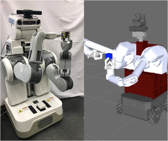
Figure 1 : Rubik’s cube manipulation can be used to benchmark robot manipulation across a wide array of algorithmic approaches and robot platforms, such as the PR2 and HERB.

This figure's primary purpose is to visually demonstrate the applicability and generality of the proposed "Rubik's cube manipulation" as a benchmark for robot manipulation, across a wide range of algorithmic approaches and robot platforms. It achieves this by side-by-side illustration of two different robot platforms performing the task of manipulating a Rubik's cube, explaining how the method operates.

The left side of the image shows an actual PR2 robot executing a Rubik's cube manipulation task. This robot has a dual-armed configuration, and its right arm (from the observer's perspective) has an end effector (gripper) firmly holding a standard 3x3 Rubik's cube. The robot's visual sensors (likely located on its head) are used to perceive the cube's state and position. The entire scene is a real-world experimental setup with a simple background, highlighting the robot and the task itself. This represents the application of the benchmark on physical hardware.

The right side of the image displays a simulated scenario, showing another robot platform (identified by the caption as the HERB robot) performing the same Rubik's cube manipulation task. This simulated environment is typically used for rapid iteration, testing, and validation of algorithms because it offers a controllable environment and lower costs. In the image, HERB's arms are also interacting with the Rubik's cube, although the details might differ from the PR2 on the left, the core task remains identical. The grid background in the simulation environment aids in localization and measurement.

These two side-by-side images collectively reveal how the method operates: 1. Task Definition: The core task is to manipulate the Rubik's cube, which involves precisely grasping, moving, and placing its various faces to achieve a specific goal (like solving the cube or executing a particular pattern). 2. Platform Agnosticism: The method is not dependent on a specific robot platform. The image showcases two different robots, PR2 and HERB, with varying mechanical structures and perceptual capabilities, yet both can perform this benchmark test. 3. Algorithm Generality: The benchmark is designed to evaluate the performance of various algorithmic approaches. Whether based on vision-based planning, pre-touch sensing, or other strategies, they can be compared within this unified task framework. 4. Data/Information Flow: For each robot platform, the information flow is roughly as follows: * Perception: The robot perceives the initial state and position of the Rubik's cube through its sensors (e.g., cameras, lidar). * Planning: Based on the perceived information, a sequence of action plans is formulated to achieve precise manipulation of the cube. * Execution: The robot executes the planned actions, physically interacting with the Rubik's cube through its end effector. * Evaluation: The algorithm's performance is assessed based on metrics such as the final state of the cube and the time taken to complete the task. 5. Implementation of the Benchmark: As depicted, implementing this benchmark requires only a standard 3x3 Rubik's cube and a flat surface (like a table). This allows different research teams to easily reproduce and compare results.

This image is not a traditional results figure with coordinates, specific comparative values, or statistical conclusions. Instead, it is a conceptual diagram illustrating how the "Rubik's cube manipulation" benchmark can be applied to different robot platforms. It clearly indicates that this method provides a standardized task that can be used to measure and compare the performance of different algorithms and robots in terms of precise and sequential manipulation. By showcasing the PR2 and HERB, two representative robot platforms, the figure effectively communicates the broad applicability of this benchmark.

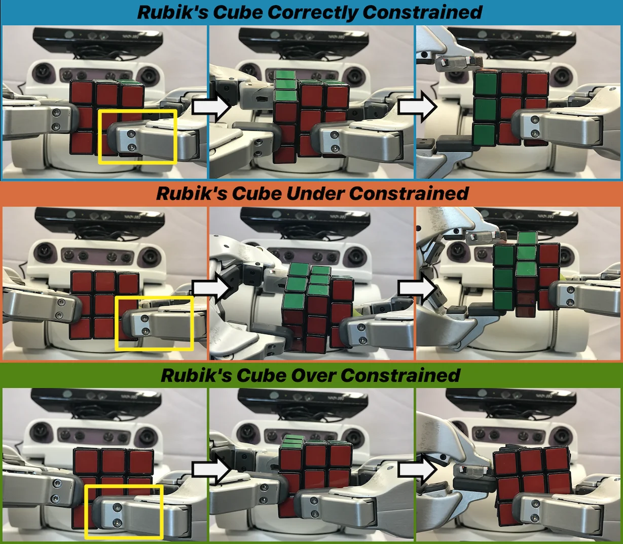
Figure 2 : The robot must precisely position its grippers to rotate the left column of the Rubik’s cube while constraining the middle and right columns in place. Top Row: The robot correctly positions its grippers: it is constraining the two right columns of the cube. The yellow box highlights the position of the constraining gripper. Middle Row: The robot only touches one column of the Rubik’s cube and therefore fails to constrain its middle column. Bottom Row: The right gripper is touching all three columns of the cube; this prevents the left gripper from rotating the left column of the cube.

This figure (Figure 2) is from the paper "Benchmarking Robot Manipulation with the Rubik's Cube" and clearly illustrates how robotic grippers can correctly, insufficiently, or excessively constrain different columns of a Rubik's Cube to perform specific actions (such as rotating the left column, as shown in the figure). The figure is structured into three horizontal sections, each containing three consecutive images that show the progression of an operation sequence. Arrows indicate the order of operations, from left to right.

  1. Top Row (Blue Background Title: "Rubik's Cube Correctly Constrained"):

    • First Column (Left Image): Shows the robot correctly positioning its grippers. A yellow box highlights the gripper used for constraining (usually the right gripper). Here, the robot's two grippers are in contact with and constraining the middle and right columns of the cube. The goal is to rotate the left column while keeping the middle and right columns fixed.
    • Second Column (Middle Image): Displays an intermediate state during the operation. The left gripper is attempting to rotate the left column (you can see changes in the color blocks of the left column, such as the appearance of green blocks), while the middle and right columns remain stationary due to being correctly constrained.
    • Third Column (Right Image): Shows the state after the operation is completed. The left column has been successfully rotated, while the middle and right columns remain in their original positions because they were correctly constrained. This indicates that the robot successfully executed the rotation of the left column without affecting the other columns.
  2. Middle Row (Orange Background Title: "Rubik's Cube Under Constrained"):

    • First Column (Left Image): Shows the robot's grippers in an incorrect position, leading to insufficient constraint. The yellow box again highlights the gripper used for constraining. In this case, the gripper seems to be in contact with only one column of the cube (possibly the middle or right column) instead of two.
    • Second Column (Middle Image): Displays the process of attempting to rotate the left column. Due to insufficient constraint, when the left gripper rotates the left column, the middle column also moves (you can see changes in the color blocks of the middle column). This shows that the robot failed to effectively fix the middle column of the cube.
    • Third Column (Right Image): Shows the state after the operation. The left column has been rotated, but the middle column has also moved unexpectedly. This indicates that due to insufficient constraint, the robot was unable to precisely perform the task of rotating only the left column.
  3. Bottom Row (Green Background Title: "Rubik's Cube Over Constrained"):

    • First Column (Left Image): Shows the robot's grippers in a position that leads to excessive constraint. The yellow box highlights the gripper used for constraining. In this situation, the right gripper seems to be in contact with all three columns of the cube (left, middle, and right).
    • Second Column (Middle Image): Displays the process of attempting to rotate the left column. Due to the right gripper excessively constraining all columns, the left gripper cannot freely rotate the left column, or the rotation movement is severely hindered. You can see that there is little or no change in the color blocks of the left column, or the change is not as expected.
    • Third Column (Right Image): Shows the state after the operation. The left column has been rotated very little or at an incorrect angle. This indicates that excessive constraint prevented the robot from performing the required precise action.

Explanation of How the Method Works: This figure reveals the importance of precise constraint when a robot manipulates a Rubik's Cube. The method is as follows: To rotate a column of the cube (for example, the left column), the robot needs to use one gripper to apply rotational force (active gripper) and another gripper to fix the other columns of the cube (constraining gripper). * Correct Constraint (Top Row): The constraining gripper stably fixes the columns that do not need to move (middle and right columns), allowing the active gripper to successfully rotate the target column (left column) without affecting other parts. * Insufficient Constraint (Middle Row): The constraining gripper does not fix all the columns that need to be fixed, causing the other columns to move along when the target column is rotated, thus making it impossible to achieve precise operation. * Excessive Constraint (Bottom Row): The constraining gripper fixes too many columns, even including the target column that needs to be rotated, which hinders the movement of the active gripper and prevents it from effectively rotating the target column.

By comparing these three situations, the figure clearly shows that correct constraint is the key to achieving precise Rubik's Cube manipulation. The arrows indicate the order of operations: from the initial gripper position, to performing the rotation action, and then to observing the result.

Conclusion: This figure intuitively explains, through comparing the three situations of correct, insufficient, and excessive constraint, that precise control of grippers to constrain the non - target parts of the cube is crucial for successfully performing specific actions (such as rotating a column) when a robot manipulates a Rubik's Cube. Correct constraint allows the rotation of the target column, while insufficient or excessive constraint will lead to operation failure or a decrease in precision.

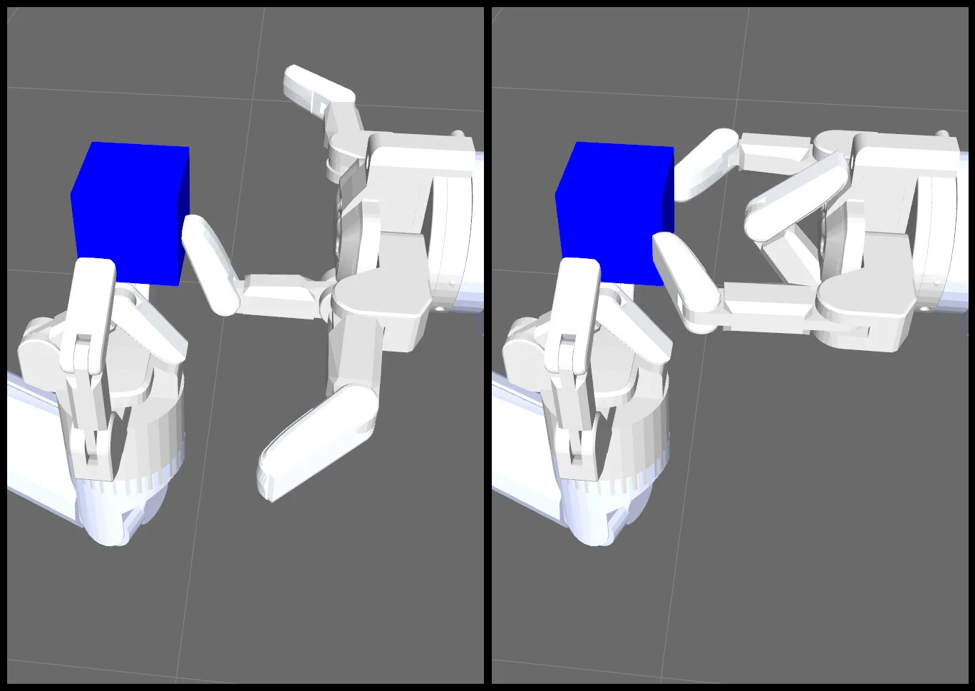
Figure 3 : HERB’s simulated Barrett hands manipulate the Rubik’s cube in blue. Left: The right gripper uses a push-grasp to make contact with the Rubik’s cube. Upon making contact, the right gripper reaches the desired pre-grasp. Right: The right gripper closes its outer fingers to transition from pre-grasp to grasp.

This figure (Figure 3) from the paper "Benchmarking Robot Manipulation with the Rubik's Cube" illustrates two key steps of HERB's simulated Barrett hands manipulating a blue Rubik's cube. The core purpose of this figure is to visually explain a specific grasping strategy, namely the "push-grasp" method.

First, let's examine the left image: - Main Components: The image shows a simulated robotic arm of HERB equipped with a Barrett hand (a type of multi-fingered robotic hand). This hand is interacting with a blue Rubik's cube. - Action Description: According to the figure caption, the left image demonstrates that the "right gripper uses a push-grasp to make contact with the Rubik's cube." Specifically, we can see one or more fingers of the gripper (possibly the outer fingers) applying a pushing force to one face of the cube. The purpose of this pushing force is to adjust the cube's position or orientation to prepare for the subsequent grasp. - State: After making contact with the cube, the right gripper reaches the "desired pre-grasp." This means that the gripper's fingers have adjusted to the appropriate position and orientation, ready to grasp the cube, but not yet fully closed.

Next, let's look at the right image: - Main Components: It is still the same robotic arm and Barrett hand, as well as the same blue Rubik's cube. - Action Description: The right image shows that the "right gripper closes its outer fingers to transition from pre-grasp to grasp." We can clearly see that the outer fingers of the gripper have closed, firmly grasping one face of the cube. This action marks the transition from the preparatory grasp to the actual grasp. - State: At this point, the gripper has successfully grasped the cube, completing the grasping action.

This figure reveals how the method works in detail: 1. Push-Grasp Strategy: This method first pushes the cube to adjust its position or orientation, making it more suitable for grasping. The pushing action helps the robot better control the cube's movement, especially in situations requiring precise alignment. 2. Pre-Grasp State: After pushing, the gripper adjusts the position and orientation of its fingers to reach a pre-grasp state. This state is a prelude to the grasping action, ensuring that the gripper can grasp the object in the optimal position and orientation. 3. Grasping Action: Finally, the gripper closes its fingers to complete the grasping action. This process requires precise control and coordination to ensure that the object is stably grasped without slipping or damage.

By comparing the two images, we can clearly see the implementation process of the push-grasp strategy. The left image shows the steps of pushing and pre-grasping, while the right image shows the final state of the grasp. This method is very important in robotic manipulation because it can adjust the object's position without direct contact, thereby improving the accuracy and stability of the grasp.

In summary, this figure visually explains the specific operation of the push-grasp strategy by showing two key steps of HERB's simulated Barrett hands manipulating a blue Rubik's cube. This method, through the steps of pushing and pre-grasping, ultimately achieves a stable grasp of the cube, demonstrating the robot's capability in precise manipulation.

← → flip · ↑ ↓ scroll notes · Esc exit