🌊 Tide

Information moves like the tide. We pick the waves worth studying.

中文

← Today's tide

Published 2026-07-10 · Seoul National University · Minhyuk Hwang, Sangmin Kim, Seunguk Do et al.

4D Human-Scene Reconstruction from Low-Overlap Captures

arXiv · HuggingFace · ▲53

Abstract (verbatim)

Existing volumetric capture of dynamic human performance achieves high fidelity with dense camera arrays. However, in real-world scenarios, only a handful of low-overlap cameras are available, which degrades the output quality and leaves large areas unobserved. Recent 4D reconstruction methods have focused on low-overlap settings, yet they still produce noticeable artifacts in under-observed regions. Video diffusion models have emerged as another option, but they show geometrically inconsistent results for humans. To address these limitations, we propose StudioRecon, a pipeline that reconstructs 4D human scenes from sparse, low-overlap cameras by decoupling background and humans. We densify background supervision by synthesizing hundreds of camera-controlled novel views with a video diffusion model. We also robustly initialize deformable Gaussian humans with cross-view identity association and triangulated multi-view keypoint fitting. Finally, our recursive enhancement module with motion-adaptive consistency injection harmonizes the composed output, thereby further avoiding remaining artifacts. We achieve state-of-the-art novel view synthesis across four real-world datasets and demonstrate applications such as novel trajectory rendering and human replacement.

Background

Background Analysis

1. Technical Context and Real-World Needs
High-fidelity 4D human scene reconstruction is critical for entertainment (e.g., virtual production), sports broadcasting, and metaverse applications. Professional systems achieve high-quality dynamic capture using dense camera arrays, but they require dozens to hundreds of cameras in controlled environments. However, real-world scenarios (e.g., gyms, homes) often have only a few uncalibrated, low-overlap cameras, with frequent occlusions and multi-person interactions. This "in-the-wild studio" setting demands technology that can generate coherent, artifact-free reconstructions under limited camera conditions while supporting practical tasks like novel view synthesis, trajectory rendering, or human replacement.

2. Limitations of Previous Methods
Existing approaches face two core issues:
- Entanglement of Background and Human Representations: Traditional joint reconstruction methods (e.g., 4D Gaussian Splatting) suffer from artifacts in unobserved regions due to intertwined errors between backgrounds and humans.
- Geometric Consistency and Coverage Gaps: While video diffusion models can synthesize plausible backgrounds, they fail to ensure consistent human motion in multi-person scenes; methods relying on parametric models (e.g., SMPL) struggle with initialization in sparse views due to occlusions and parallax.

3. Proposed Solution
The paper introduces StudioRecon, a decoupled reconstruction framework that addresses these problems by separating background and human reconstruction:
- Background Reconstruction: A camera-controlled video diffusion model synthesizes hundreds of novel views from sparse inputs, providing dense supervision to prevent degradation in unobserved regions.
- Human Reconstruction: Leveraging geometric priors from parametric models (e.g., SMPL), it robustly initializes dynamic humans via cross-view identity association and multi-view keypoint triangulation.
- Temporal Coherence Enhancement: A single-step diffusion model with motion-adaptive consistency injection eliminates static artifacts and ensures frame-by-frame coherence, addressing flickering in traditional methods.

4. Key Differences from Prior Work
- Decoupled Strategy: Unlike previous joint optimizations, this work exploits complementary strengths of diffusion models (backgrounds) and parametric models (humans) to avoid representation entanglement.
- Multi-View Human Estimation: Spatial and pose affinity-based keypoint triangulation improves robustness in sparse views.
- Temporal Consistency: It is the first to combine single-step diffusion with motion-adaptive injection for long-term coherent rendering in dynamic scenes.

This method achieves SOTA performance on real-world datasets (EgoHumans, Harmony4D) and supports applications like novel trajectory rendering and human replacement, filling the technical gap in high-fidelity 4D reconstruction under low-overlap constraints.
Method, Figure by Figure

M E T H O D1 / 20

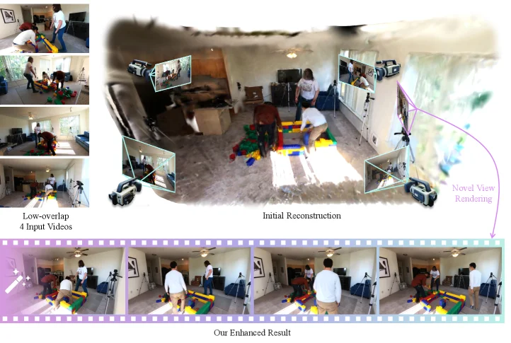
Figure 1. Given only as few as four sparse, low-overlap input videos (left), StudioRecon first reconstructs decoupled Gaussians for background and humans (right). The reconstructed Gaussians enable rendering from novel viewpoints, and our recursive enhancement module further refines the rendered output (bottom).

This figure clearly illustrates the core workflow and results of the StudioRecon method proposed in the paper "4D Human-Scene Reconstruction from Low-Overlap Captures".

First, look at the top-left corner of the image, labeled "Low-overlap 4 Input Videos". This section shows four input videos, which are characterized by having very little overlap between their shooting angles, known as a "low-overlap" setup. This is a common scenario in real-world situations, such as using a small number of cameras to capture a scene from different directions, but with limited cross-over in their fields of view. These videos serve as the raw data input for the entire reconstruction process.

Next, the upper-middle part of the image is labeled "Initial Reconstruction". This section displays a 3D reconstructed scene of a room, including both people and the background. You can see that this initial reconstruction attempts to fuse information from the four low-overlap videos into a preliminary 3D model. Within this initial reconstruction scene, several small windows are embedded, showing the results of rendering this initial reconstruction from different perspectives, which corresponds to the caption's mention of "reconstructed Gaussians enable rendering from novel viewpoints". Additionally, there is a purple arrow pointing to the right, labeled "Novel View Rendering", further indicating that the results of the initial reconstruction can be used to generate images from new viewpoints, although some imperfections might still be present at this stage.

Then, look at the bottom part of the image, labeled "Our Enhanced Result". This section showcases the final results after processing by StudioRecon's recursive enhancement module. The bottom row contains a series of consecutive images, displaying the scene rendered from different perspectives or at different time points. Compared to the "Initial Reconstruction", "Our Enhanced Result" appears clearer, more coherent, and richer in detail. This indicates that StudioRecon's method, through its recursive enhancement module, further optimizes the initial reconstruction results, reducing artifacts and improving rendering quality. This process corresponds to the caption's statement that "our recursive enhancement module further refines the rendered output".

The overall flow of the figure can be understood as follows: first, four low-overlap input videos are used as the data source; then, the StudioRecon method processes these videos to perform decoupled reconstruction of the background and humans, obtaining an initial 3D Gaussian representation; next, these Gaussians are used for novel view rendering, producing the initial rendered results; finally, the recursive enhancement module further optimizes these novel view renderings to achieve high-quality final rendered results.

This figure reveals how the StudioRecon method works: it decouples the reconstruction of the background and humans, uses a video diffusion model to synthesize a large number of camera-controlled novel views to enhance background supervision, and robustly initializes deformable Gaussian humans using cross-view identity association and multi-view keypoint triangulation. Finally, a recursive enhancement module with motion-adaptive consistency injection harmonizes the composed output, thereby avoiding remaining artifacts. The "Initial Reconstruction" in the figure shows an intermediate step of the method, while "Our Enhanced Result" demonstrates the high-quality rendering achieved by the method, proving the effectiveness of StudioRecon in 4D human-scene reconstruction under low-overlap settings.

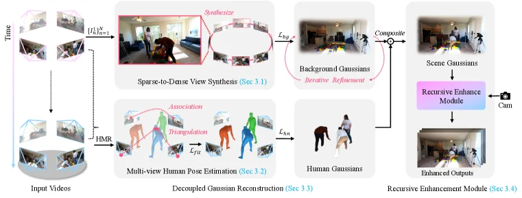
Figure 2. Overview of the proposed StudioRecon. Our pipeline consists of four stages: (1) sparse-to-dense view synthesis using camera-controlled video diffusion, (2) multi-view human pose estimation, (3) decoupled Gaussian reconstruction for background and humans, and (4) a recursive enhancement module.

This figure illustrates the workflow of the StudioRecon method proposed in the paper "4D Human-Scene Reconstruction from Low-Overlap Captures," clearly detailing the four main stages and data flow from input videos to the final enhanced output.

The process begins on the left with "Input Videos." These are captured from multiple camera viewpoints at different time frames (indicated by "Time"), as shown by the images at the top and bottom left, connected by dashed arrows representing temporal progression.

The first major stage is "Sparse-to-Dense View Synthesis (Sec 3.1)." This stage takes sparse views from the input videos (e.g., the few small images at the top, marked as {I_t}^N_{n=1}) and uses "camera-controlled video diffusion" to synthesize a large number of new virtual views, creating a dense set of views, depicted as the circular sequence of images in the middle with the label "Synthesize." The goal is to enhance background supervision using a diffusion model to address the issue of missing information due to low-overlap cameras. The synthesized dense views are compared with reference views (or real views), calculating a loss L_bg (background loss), and "Iterative Refinement" is applied to optimize "Background Gaussians," resulting in a refined background representation.

In parallel, the second major stage is "Multi-view Human Pose Estimation (Sec 3.2)." This stage also takes input from the videos. It first performs "Association" to link human identities across different views, ensuring correct recognition of the same person in various camera perspectives. Then, "Triangulation" is used to initialize "deformable Gaussian humans" through multi-view keypoint fitting. This process involves computing a loss L_fit (fitting loss) to optimize the estimated human pose and shape. The final output is "Human Gaussians," represented by the human models shown in the lower-middle part of the figure.

The third stage is "Decoupled Gaussian Reconstruction (Sec 3.3)." Here, the "Background Gaussians" from the first stage and the "Human Gaussians" from the second stage are combined (labeled "Composite") to form "Scene Gaussians," which represent the complete scene including both background and humans. The key here is to handle the background and humans separately before merging them to improve reconstruction quality.

The final stage is the "Recursive Enhancement Module (Sec 3.4)." This stage takes "Scene Gaussians" as input. The recursive enhancement module further harmonizes the composited output by injecting "motion-adaptive consistency" to avoid remaining artifacts. After processing by this module, the final "Enhanced Outputs" are produced, as shown in the bottom-right image, which exhibits higher quality and consistency.

The overall data flow is: Input Videos -> Sparse-to-Dense View Synthesis (for background) and Multi-view Human Pose Estimation (for humans) -> Decoupled Gaussian Reconstruction (combining background and humans) -> Recursive Enhancement Module (optimizing output). Each stage has specific objectives and processing methods, and by decoupling the background and humans and utilizing video diffusion models and multi-view pose estimation techniques, the method achieves high-quality 4D human-scene reconstruction from sparse, low-overlap camera captures.

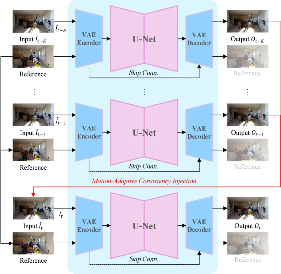
Figure 3. Overview of our recursive enhancement module (Sec. 3.4 ).

This figure illustrates the recursive enhancement module (as described in Section 3.4 of the paper "4D Human-Scene Reconstruction from Low-Overlap Captures"). The module is designed to improve the quality of 4D human-scene reconstruction by iteratively refining outputs using motion-adaptive consistency injection, thereby reducing artifacts.

Core Idea and Flow Overview: The core idea is to recursively process a sequence of input images, leveraging the results from previous frames to enhance the current frame's output. The process starts with earlier frames and progressively moves towards the target frame. Each frame's processing involves encoding, decoding, and information fusion with other frames (particularly reference frames).

Component and Data Flow Details:

  1. Input Section (Left Side):

    • Input \( \hat{I}{t-K} \), \( \hat{I}{t-1} \), \( \hat{I}_t \): These represent input images at different time steps. For example, \( \hat{I}{t-K} \) is an earlier frame, \( \hat{I}{t-1} \) is the previous frame, and \( \hat{I}_t \) is the current target frame. These inputs might be preliminary or estimated images.
    • Reference: Each input image is paired with a "Reference" image. These reference images could come from other camera viewpoints or higher-quality baseline images, providing additional context or supervision.
  2. Processing Units (Middle Section):

    • VAE Encoder: Each input image first passes through a VAE (Variational Autoencoder) encoder. The encoder compresses the input image into a latent space representation, capturing key features.
    • U-Net: The output of the VAE encoder is fed into a U-Net architecture. U-Net is a convolutional neural network commonly used for image segmentation and image-to-image translation, featuring an encoder-decoder structure with skip connections. In this module, the U-Net processes the latent representation, potentially denoising, enhancing, or generating new features.
    • Skip Conn. (Skip Connections): The dashed arrows labeled "Skip Conn." represent skip connections, which directly pass feature maps from the encoder part of the U-Net to the decoder part. This helps preserve fine-grained spatial details during decoding.
    • VAE Decoder: The output of the U-Net is sent to a VAE decoder. The decoder converts the latent space representation back to the image space, generating the final output image.
    • Output \( O_{t-K} \), \( O_{t-1} \), \( O_t \): These are the output images from each processing unit. For instance, \( O_{t-K} \) is the result of processing \( \hat{I}{t-K} \), \( O{t-1} \) is the result of processing \( \hat{I}_{t-1} \), and \( O_t \) is the final output for the target frame \( \hat{I}_t \).
  3. Recursion and Consistency Injection (Motion-Adaptive Consistency Injection):

    • The red arrows and box highlight "Motion-Adaptive Consistency Injection." This indicates that the processing of the current frame (e.g., \( \hat{I}t \)) depends on the outputs from previous frames (e.g., \( O{t-1} \) or \( O_{t-K} \)).
    • Specifically, when processing \( \hat{I}t \), it uses not only its own input and reference images but also the previously generated output (e.g., \( O{t-1} \) or its corresponding reference image) as additional input or supervision. This recursive mechanism allows the module to leverage temporal correlations, ensuring motion consistency and visual coherence between adjacent frames.
    • "Motion-Adaptive" means this consistency injection is dynamically adjusted based on the motion, better adapting to dynamic changes in the scene.

How the Method Works: The recursive enhancement module operates as follows: * Initialization: It starts with the earliest frame (e.g., \( \hat{I}{t-K} \)), processing its input and reference images to generate an initial output \( O{t-K} \). * Recursive Processing: Subsequently, it processes subsequent frames (e.g., \( \hat{I}{t-1} \)). At this stage, besides its own input and reference images, it utilizes the previously generated output (e.g., \( O{t-K} \) or its reference image) to assist in the current frame's processing. This step, enabled by motion-adaptive consistency injection, ensures the current frame's output is consistent with previous frames in terms of motion and appearance. * Target Frame Processing: Finally, the target frame \( \hat{I}t \) is processed. Similarly, it uses its own input and reference images, along with all previously processed information (especially \( O{t-1} \)), to generate a high-quality output \( O_t \). * Effect: Through this recursive approach, the module progressively refines and enhances the output images, reducing artifacts and improving overall quality and temporal consistency. Each frame's processing benefits from information from previous frames, achieving more stable and accurate 4D reconstruction.

Conclusion: This figure clearly demonstrates how the recursive enhancement module improves the quality of 4D human-scene reconstruction by iteratively refining outputs using motion-adaptive consistency injection. This method effectively addresses artifact issues in low-overlap camera setups by leveraging temporal information and ensuring inter-frame consistency.

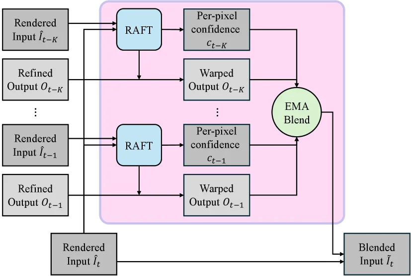
Figure 4. Schematic of motion-adaptive consistency injection. For each frame, RAFT computes backward flow to warp previous enhanced outputs, which are blended with the current input via per-pixel confidence-weighted EMA before single-step diffusion.

This diagram illustrates the principle of the "Motion-Adaptive Consistency Injection" module, a core part of the StudioRecon method proposed in the paper "4D Human-Scene Reconstruction from Low-Overlap Captures," used to enhance the coherence of reconstruction results and reduce artifacts.

Let's analyze the various components in the diagram and their data flow from left to right and top to bottom:

  1. Input Section:

    • On the far left, there are multiple input sources, including "Rendered Input Îₜ₋ₖ", "Refined Output Oₜ₋ₖ", "Rendered Input Îₜ₋₁", "Refined Output Oₜ₋₁", and at the bottom, "Rendered Input Îₜ". Here, Î represents rendered input images, and O represents refined outputs. The subscripts t-k, t-1, and t indicate different time frames, where k is a time step (e.g., k=2 means the frame two steps prior). This indicates that the module processes a sequence of temporally continuous frames.
  2. Core Processing Unit - RAFT:

    • There are two (or more, indicated by ellipsis) blue "RAFT" modules in the diagram. RAFT is an optical flow estimation algorithm. For each historical frame (such as Îₜ₋ₖ and Îₜ₋₁), RAFT calculates the reverse optical flow from the current frame (Îₜ) to that historical frame. Reverse optical flow means predicting motion from the current frame to the historical frame.
  3. Warped Output:

    • The output of the RAFT modules (the optical flow field) is used to "warp" (Warp) the corresponding historical refined outputs. For example, the RAFT output for Îₜ₋ₖ warps Oₜ₋ₖ to obtain Warped Output Oₜ₋ₖ; similarly, the RAFT output for Îₜ₋₁ warps Oₜ₋₁ to obtain Warped Output Oₜ₋₁. This process adjusts the refined results from historical frames to the position of the current frame based on the estimated motion, so they can be fused with the current frame.
  4. Per-pixel Confidence:

    • While calculating the optical flow, each RAFT module also outputs a "per-pixel confidence" map (such as cₜ₋ₖ, cₜ₋₁). This confidence map assigns a weight to each pixel, indicating the reliability of the optical flow estimation at that pixel. Pixels with high confidence are given more importance in the subsequent fusion process.
  5. EMA Blend:

    • All "warped outputs" (such as Warped Output Oₜ₋ₖ, Warped Output Oₜ₋₁) and their corresponding "per-pixel confidence" (such as cₜ₋ₖ, cₜ₋₁) are fed into a module called "EMA Blend". EMA stands for Exponential Moving Average. This module performs a weighted fusion of multiple warped historical outputs based on their confidence, generating a consistent intermediate result. This process considers the reliability of different historical frames, thereby improving the robustness of the fusion.
  6. Blended Input:

    • The output of the "EMA Blend" module is combined with the "Rendered Input Îₜ" at the bottom (the rendered input of the current frame) to generate the final "Blended Input Î̂ₜ". This "Blended Input Î̂ₜ" is the result after motion-adaptive consistency injection and will serve as the input for the next stage (e.g., the input for single-step diffusion).

Summary of the Specific Workflow of the Method:

The goal of this module is to enhance the reconstruction quality of the current frame by utilizing information from previous frames and ensure temporal consistency. * Step One: Motion Estimation. For the current frame Îₜ and multiple previous frames (such as Îₜ₋₁, Îₜ₋ₖ), the reverse optical flow from the current frame to the previous frames is calculated using the RAFT algorithm. * Step Two: Historical Frame Alignment. Using the calculated optical flow, the refined outputs of the previous frames (Oₜ₋₁, Oₜ₋ₖ) are warped to the spatial position of the current frame, obtaining aligned outputs (Warped Output Oₜ₋₁, Warped Output Oₜ₋ₖ). * Step Three: Confidence-Weighted Fusion. A per-pixel confidence is calculated for each aligned output. Then, using the Exponential Moving Average (EMA) method, all aligned outputs are weighted and fused based on these confidences to obtain a consistent intermediate result. * Step Four: Fusion with Current Frame. This consistent intermediate result is fused with the rendered input of the current frame Îₜ to generate the final "Blended Input Î̂ₜ".

In this way, the method can effectively integrate information from previous frames into the reconstruction of the current frame, thereby reducing artifacts caused by low-overlap cameras or motion and improving the temporal consistency and overall quality of the reconstruction results. This module is specifically designed to handle dynamic scenes, ensuring that the motion of people or objects between consecutive frames is smooth and consistent.

Parts that are unclear or uncertain in the diagram are handled according to the caption or skipped; for example, the specific details of "single-step diffusion" are not shown in this diagram.

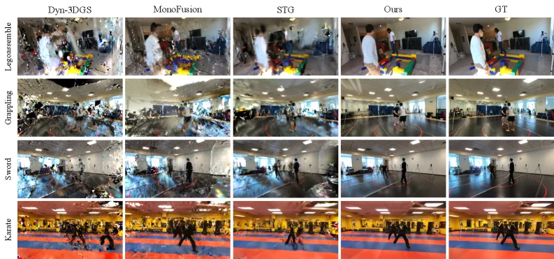
Figure 5. Qualitative comparison on 360 ∘ scenes ( Legoassemble , Grappling , Sword , Karate ). Our method produces sharper backgrounds and more robust human reconstructions than baselines.

This figure (Figure 5) presents the qualitative comparison results from the paper "4D Human-Scene Reconstruction from Low-Overlap Captures," showcasing the reconstruction performance of different methods when processing 360-degree scenes (Legoassemble, Grappling, Sword, Karate).

Figure Structure:

  • Top Row: Lists the method names from left to right: Dyn-3DGS, MonoFusion, STG, Ours (our method), and GT (Ground Truth, the real-world reference). These represent the algorithms or benchmarks being compared.
  • Left Column: Lists four test scenes: Legoassemble (Lego assembly), Grappling (wrestling), Sword (swordplay), and Karate (karate). Each scene occupies a row, displaying reconstruction results for different methods.

Each cell contains the reconstruction result of a specific method for a given scene. Let’s analyze them row by row:

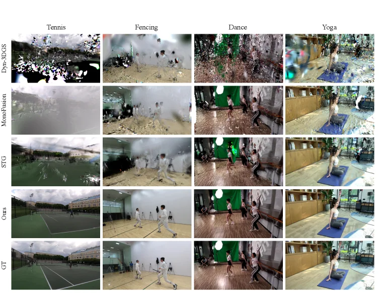
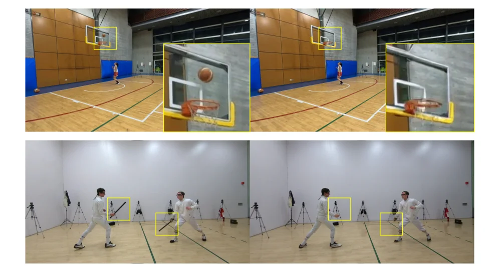
Figure 6. Additional qualitative comparison ( Tennis , Fencing , Dance , Yoga ) from EgoHumans, Mobile Stage, and SelfCap. Our method produces sharper reconstructions with better human-scene separation. Dance © Xu et al. (Mobile Stage); Yoga © Xu et al. (SelfCap), used with permission.

This figure (Figure 6) is a key result presentation from the paper "4D Human-Scene Reconstruction from Low-Overlap Captures," visually demonstrating the performance of the authors' proposed method compared to existing advanced methods across different datasets.

First, let's interpret the structure of the figure. It is a grid layout with 5 rows and 5 columns. * Columns (from left to right): Represent different datasets or scene categories: "Tennis," "Fencing," "Dance," and "Yoga." These scenes are selected to test the methods' performance under different dynamic human activities and environments. * Rows (from top to bottom): Represent different reconstruction methods or benchmarks. From top to bottom, they are: * Dyn-3DGS: A dynamic reconstruction method based on 3D Gaussian Splatting. * MonoFusion: A dynamic reconstruction method using monocular or multi-view inputs. * STG: Likely represents a specific spatio-temporal modeling method (the exact name should be referenced from the paper). * Ours: This is the authors' proposed method (StudioRecon). * GT: Ground Truth, i.e., reference images of the real scene, used to measure the accuracy of the reconstruction results.

The flow and logic of comparison are as follows: For each scene category (column), it is input into different reconstruction methods (rows), and then the output reconstruction results of each method are compared with the real scene (GT).

This figure reveals how the authors' method works and its advantages through comparison: 1. Problem Background: Existing 4D human scene reconstruction methods, especially in low-overlap camera setups (where only a few cameras are available with minimal field-of-view overlap), often produce noticeable artifacts in unobserved regions or have overall low reconstruction quality. Video diffusion models, while offering an alternative approach, show geometrically inconsistent results for humans. 2. Author's Method Solution: The method proposed by the authors (Ours) aims to address these issues. It performs 4D reconstruction by decoupling the background and the human. Specifically: * For the background, it uses a video diffusion model to synthesize hundreds of new camera-controlled views, thereby enhancing background supervision. * For the human, it robustly initializes deformable Gaussian human models using cross-view identity association and triangulated multi-view keypoint fitting. * Finally, a recursive enhancement module harmonizes the composed human and background through motion-adaptive consistency injection, further avoiding remaining artifacts. 3. Method Effect from the Figure: * In the "Ours" row (fourth row), its reconstruction results are significantly superior to other methods (Dyn-3DGS, MonoFusion, STG) in all four scenes. * For example, in the "Tennis" scene, the "Ours" reconstruction clearly shows the tennis court, players, and net with rich details and almost no artifacts. In contrast, the results from Dyn-3DGS and MonoFusion above are very blurry and noisy, and the result from STG, while improved, is still not clear enough. * In the "Fencing" scene, "Ours" clearly reconstructs the movements and clothing details of the two fencers, as well as the background walls and floor. The results from other methods appear blurry or incomplete. * In the "Dance" scene, "Ours" accurately reconstructs the dancers' poses and clothing, as well as the green screen and environment in the background. Results from other methods are either blurry or show artifacts at human edges or in the background. * In the "Yoga" scene, "Ours" clearly reconstructs the yoga practitioner's pose and mat, with clear details of the background room. Results from other methods appear blurry or have unnatural distortions. 4. Comparison with Benchmarks: * The "GT" row (fifth row) provides the ideal reconstruction result as a judging standard. * It is clear that the results in the "Ours" row are closest to the "GT" row in terms of clarity, detail preservation, and overall realism. * The original caption from the paper states: "Our method produces sharper reconstructions with better human-scene separation." (我们的方法产生了更清晰的重建结果,并且人-景分离效果更好。) This figure intuitively confirms this point. For example, in the "Dance" scene, the boundary between the human and the background (e.g., the green screen) might be unclear in other methods, while the "Ours" result shows a clearer separation between human and scene.

Conclusion: This figure, through qualitative comparison, powerfully demonstrates the superiority of the authors' proposed method (Ours) in 4D human scene reconstruction under low-overlap camera settings. It can produce clearer, more detailed, and better human-scene-separated reconstruction results, effectively solving the problem of artifacts in unobserved regions produced by existing methods. Each cell in the figure represents the reconstruction output of a specific method in a specific scene. Through row-by-row and column-by-column comparisons, readers can intuitively understand the performance differences between different methods and the advantages of the authors' method.

It is important to note that the information "Dance © Xu et al. (Mobile Stage); Yoga © Xu et al. (SelfCap), used with permission." at the bottom of the figure indicates that the dance and yoga datasets are from Xu et al.'s Mobile Stage and SelfCap research, respectively, and permission has been obtained for their use.

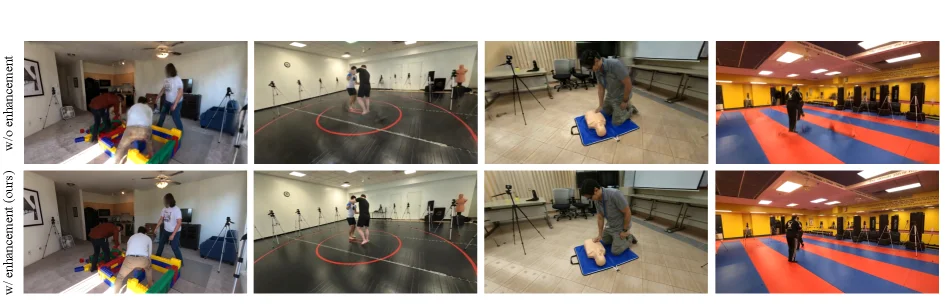
Figure 7. Ablation on recursive enhancement (Sec. 3.4 ). Raw renders (left) contain blur and geometric instabilities. Enhancement (right) produces clean, harmonized outputs.

This figure (Figure 7) illustrates the ablation study for the recursive enhancement module (Section 3.4) proposed in the paper. It corresponds to the content in Section 3.4 and visually demonstrates the effectiveness of this module by comparing the results with and without it.

Let's break down the components and information presented in the image:

  1. Overall Layout:

    • The image is organized in a 2-row by 4-column grid.
    • The top row is labeled "w/o enhancement" (without enhancement), showing the original rendering results before the recursive enhancement is applied.
    • The bottom row is labeled "w/ enhancement (ours)" (with enhancement, our method), displaying the results after the recursive enhancement has been applied.
    • Each column represents the same scene or viewpoint under different processing conditions.
  2. Data or Information Flow and Comparison:

    • For each scene (each column), we first see the "without enhancement" result (top image), followed by the "with enhancement" result (bottom image). This indicates the processing flow is from top to bottom: original rendering -> applying recursive enhancement -> obtaining the enhanced rendering.
    • This side-by-side comparison allows readers to clearly see the improvements brought by the enhancement module.
  3. Revealing How the Method Works:

    • While this image itself doesn't directly show the operational mechanisms of the method (like background synthesis or human initialization), it indirectly proves the role of the recursive enhancement module through result comparison. According to the paper's abstract, the recursive enhancement module aims to "harmonize the composed output, thereby further avoiding remaining artifacts."
    • From the image, the "without enhancement" results (top row) exhibit noticeable blurriness and geometric instabilities. For example:
      • In the first scene (far left), the edges and details of the person appear blurry.
      • In the second scene, the legs and body contours of the person are not as clear.
      • In the third scene, the human pose and the details of the mannequin model look somewhat unstable or unnatural.
      • In the fourth scene, the outline of the person and the boundary with the background appear fuzzy.
    • In contrast, the "with enhancement" results (bottom row) show cleaner and more harmonious outputs. The blurriness and geometric instabilities are significantly improved. For example:
      • The edges of the people are sharper, and the details are clearer.
      • The human poses and object shapes are more stable and natural.
      • The overall image quality is higher, with fewer artifacts.
  4. Conclusion:

    • This figure clearly demonstrates the effectiveness of the recursive enhancement module. By comparing the results "without enhancement" and "with enhancement," it can be concluded that the recursive enhancement significantly improves the image quality of 4D human-scene reconstruction from low-overlap cameras, eliminating blurriness and geometric instabilities to produce cleaner and more harmonious outputs.
    • This aligns with the statement in the paper's abstract: "our recursive enhancement module... harmonizes the composed output, thereby further avoiding remaining artifacts."

In summary, this image provides a strong visual demonstration of the importance of the recursive enhancement module in improving the quality of 4D human-scene reconstruction from low-overlap camera captures. It shows how this method improves the original rendering results, making them clearer and more realistic.

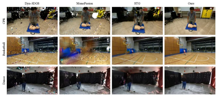
Figure 8. Qualitative results on EgoExo-4D (Grauman et al. , 2024 ) . Our method applies to diverse activities and environments.

This figure (Figure 8) is from the paper "4D Human-Scene Reconstruction from Low-Overlap Captures" and shows the qualitative results of the method on the EgoExo-4D dataset. It visually compares the performance differences of various methods in handling the dynamic human-scene reconstruction task with low-overlap camera captures, thereby highlighting the advantages of the authors' proposed method (Ours).

First, let's understand the structure of the figure. This figure is organized into a 3-row by 4-column matrix. Each row represents a different activity scene, and each column represents a different reconstruction method.

Explanation of Rows (Activity Scenes): * First Row (CPR): Shows a cardiopulmonary resuscitation (CPR) scene. We can see a person operating on a mannequin. * Second Row (Basketball): Shows a basketball court scene with a person moving on the court. * Third Row (Dance): Shows a dance scene with a person dancing.

Explanation of Columns (Reconstruction Methods): * First Column (Dyn-3DGS): These are the reconstruction results of the Dyn-3DGS method. As can be seen from the figure, when dealing with low-overlap data, there is a large amount of noise and incomplete areas in the background (for example, the ground and background objects in the CPR scene appear messy, the court lines and background in the basketball scene are blurry, and the background in the dance scene is almost unrecognizable noise). This indicates that the method performs poorly in reconstructing under-observed regions. * Second Column (MonoFusion): These are the reconstruction results of the MonoFusion method. Compared with Dyn-3DGS, the results of MonoFusion have improved in some aspects, but there are still obvious artifacts. For example, in the CPR scene, there is still unnatural blurring and missing information around the background objects (such as the yellow equipment); in the basketball scene, the texture and lines of the court are not clear enough; in the dance scene, the outline of the person and the background still appear somewhat blurry and incomplete. * Third Column (STG): These are the reconstruction results of the STG method. The results of STG look a bit smoother than the first two methods, but there are still problems. For example, in the CPR scene, the details of the person and the clarity of the background have improved, but overall it still lacks sharpness; in the basketball scene, although the court lines and the color of the background wall are clearer, there are still some unnatural transitions; in the dance scene, the shape of the person and the outline of the background are more distinct than the first two methods, but there is still a slight blur. * Fourth Column (Ours): These are the reconstruction results of the authors' proposed method (StudioRecon). By comparing with the first three methods, it can be clearly seen that the image quality in the "Ours" column is the highest. In all three scenes (CPR, Basketball, Dance), the background is clearer and more complete, with a significant reduction in noise and artifacts. The details of the person are also sharper and more accurate. For example, in the CPR scene, the floor, the equipment in the background, and the mannequin model are all very clear; in the basketball scene, the lines of the basketball court, the walls, and the windows are well reconstructed; in the dance scene, the outline of the person and the background curtain are very clear.

Revealing the Operation of the Method: This figure itself does not directly show the operation process of the method, but it indirectly illustrates the effectiveness of the method through result comparison. According to the paper abstract, the authors' method (StudioRecon) works in the following ways: 1. Decouple Background and Human: Decompose the scene reconstruction task into two parts: background reconstruction and human reconstruction. 2. Densification with Background Supervision: Use a video diffusion model to synthesize hundreds of novel views controlled by the camera to enhance the background supervision information. This allows for a more complete background reconstruction even under low-overlap camera settings. 3. Robust Human Initialization: Robustly initialize the deformable Gaussian human body model through cross-view identity association and multi-view keypoint triangulation. 4. Recursive Enhancement Module: This module, with motion-adaptive consistency injection, is used to coordinate the synthetic output and further avoid remaining artifacts.

The results in the figure clearly show that the authors' method successfully addresses the challenges of reconstruction under low-overlap camera settings, especially in terms of reconstruction quality and consistency in under-observed regions. Compared with other methods, the images in the "Ours" column show fewer artifacts, clearer details, and a more complete scene representation.

Conclusion: This figure is a qualitative comparison result chart. It visually compares the authors' proposed method (Ours) with other existing methods (Dyn-3DGS, MonoFusion, STG) on three different activity scenes (CPR, Basketball, Dance). The comparison objects are the reconstruction results of different methods in the same scene. The conclusion is obvious: the authors' method (Ours) can generate higher-quality, clearer, and more artifact-free results than existing methods in the dynamic human-scene reconstruction task with low-overlap camera captures, thus proving its effectiveness. The original caption of the figure mentions that "our method is applicable to diverse activities and environments," and this figure, by showing three different types of activity scenes, well supports this statement.

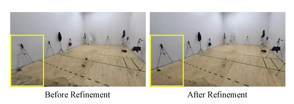
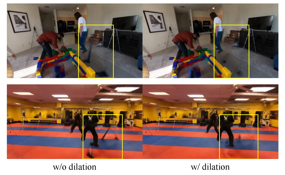
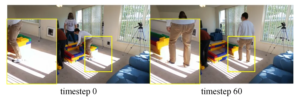
Figure 9. Effect of iterative refinement on background reconstruction (Sec. 3.3 ). Before refinement (left), undersampled regions appear blurry. After refinement (right), clarity improves. Figure 10. Ablation on motion-adaptive consistency injection (Sec. 3.4 ). Without injection (top), enhanced frames exhibit flickering. With injection (bottom), consistency improves.

This image (Figure 9) is from the paper "4D Human-Scene Reconstruction from Low-Overlap Captures" and visually demonstrates the effect of the iterative refinement technique proposed in the paper for background reconstruction, corresponding to Section 3.3.

Let's break down this figure in detail:

  1. Components and Layout:

    • The image consists of two side-by-side pictures, labeled "Before Refinement" (left) and "After Refinement" (right).
    • Each image depicts an indoor scene, likely a motion capture room, with a wooden floor, white walls, and several tripods (possibly representing cameras) positioned around.
    • In each image, a yellow rectangular box highlights a specific region, which is the area of focus for comparison.
  2. Data or Information Flow and Comparison:

    • The core of this image is to compare the quality of background reconstruction before and after the iterative refinement process.
    • Looking at "Before Refinement" (left image):
      • Within the yellow box, the area where the floor meets the wall appears blurry. Details are not sharp; for instance, the texture of the floor and the edges of objects (like tripod legs) look indistinct or incomplete. This represents the background reconstruction result without iterative refinement, where undersampled regions (areas observed by few cameras or with low overlap) tend to be blurry.
    • Looking at "After Refinement" (right image):
      • Within the same yellow box, the identical region appears much clearer. The floor texture is sharper, and object edges are more defined. This indicates that after the iterative refinement process, the quality of the background reconstruction has significantly improved.
  3. Revealing How the Method Works:

    • This image reveals how the method proposed in the paper improves background reconstruction through iterative refinement.
    • The paper states that their method (StudioRecon) reconstructs 4D human scenes by decoupling the background and humans.
    • For background reconstruction, they use a video diffusion model to synthesize hundreds of camera-controlled novel views, thereby enhancing the background supervision.
    • This figure shows the result of this enhancement process. Iterative refinement is a process that likely involves applying an optimization algorithm or model multiple times to progressively improve the reconstruction's clarity and accuracy.
    • Specifically, the refinement process targets those regions in the initial reconstruction that are undersampled due to a small number of cameras and low overlap. Through refinement, details in these regions are recovered, and blurriness is reduced, leading to a higher-quality background reconstruction.
  4. Conclusion:

    • This image clearly demonstrates that iterative refinement significantly improves the quality of background reconstruction.
    • The objects of comparison are the same scene in its state before and after refinement.
    • The conclusion is that after iterative refinement, blurry regions in the background become clearer and more detailed. This validates the effectiveness of the iterative refinement method proposed in the paper, particularly in improving the reconstruction quality of under-observed regions when dealing with data captured by low-overlap cameras.

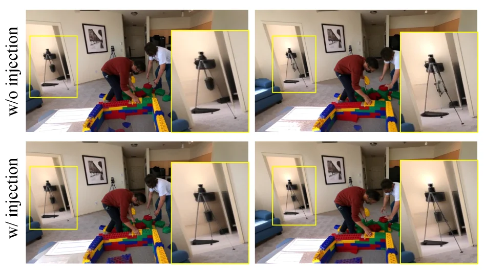
Figure 9. Effect of iterative refinement on background reconstruction (Sec. 3.3 ). Before refinement (left), undersampled regions appear blurry. After refinement (right), clarity improves. Figure 10. Ablation on motion-adaptive consistency injection (Sec. 3.4 ). Without injection (top), enhanced frames exhibit flickering. With injection (bottom), consistency improves.

This image (corresponding to Figure 10 in the paper) is an ablation study result figure, demonstrating the importance of the "motion-adaptive consistency injection" module in the proposed method. It clearly illustrates how the method works and how this specific module enhances the quality of the reconstruction results through a visual comparison.

First, let's understand the structure and components of the image:

  1. Overall Layout: The image is divided into two main sections (rows), each containing two sub-images (columns). This layout is used to compare results under different conditions.

    • Vertical Axis (Rows): The top section is labeled "w/o injection" (Without Injection), and the bottom section is labeled "w/ injection" (With Injection). This indicates that the top row shows reconstruction results without using the consistency injection module, while the bottom row shows results with the module enabled.
    • Horizontal Axis (Columns): The left and right columns show reconstructed results of the same scene at different time points or different frames. We can observe elements like people, background objects (e.g., Lego blocks, a tripod, door frames).
  2. Content in the Image:

    • Scene: The image depicts an indoor scene where two people are playing with Lego blocks. In the background, there is a tripod-mounted camera, walls, door frames, etc.
    • Yellow Boxes: There are several yellow boxes highlighting specific regions of interest. These are areas where the difference in method performance is most apparent.
      • The top-left and bottom-left yellow boxes focus on the tripod in the background.
      • The top-right and bottom-right yellow boxes focus on the door frame and part of the wall in the foreground, as well as areas near the people.
  3. Data/Information Flow and Comparison:

    • The core of this image is the comparison between reconstruction results "without injection" and "with injection."
    • Without Injection (Top Section):
      • In the "w/o injection" scenario (top row), we can observe some visual inconsistencies or "flickering." For example, in the top-right yellow box, the edges of the door frame and the lighting appear to change or be discontinuous between frames. Similarly, in the top-left yellow box, certain parts of the tripod might look unstable.
      • This inconsistency suggests that without the consistency injection, the frames generated by the method may not transition smoothly, leading to visual jitter or flicker.
    • With Injection (Bottom Section):
      • In the "w/ injection" scenario (bottom row), these inconsistencies are significantly improved. For instance, in the bottom-right yellow box, the door frame edges and lighting appear more stable and consistent. Similarly, in the bottom-left yellow box, the tripod is rendered more stably.
      • This indicates that the "motion-adaptive consistency injection" module effectively enhances temporal consistency between frames, reducing flickering and making the reconstructed video smoother and more realistic.
  4. How the Method Works (Revealed by the Image):

    • While this image itself doesn't directly show every step of the method, it indirectly illustrates the role of the "motion-adaptive consistency injection" module through the ablation experiment results.
    • The method (StudioRecon) aims to reconstruct 4D human scenes from sparse, low-overlap cameras. One challenge is ensuring temporal consistency in the generated reconstructions, especially in motion regions or areas with insufficient observation.
    • The role of the "motion-adaptive consistency injection" module is to address this issue. It introduces some form of consistency constraints or information during the reconstruction process, making the content between adjacent frames more coordinated.
    • From the image, it's clear that when this module is enabled (w/ injection), the visual quality of the reconstruction results is higher, particularly in areas prone to inconsistency (e.g., near moving humans or in background regions with significant lighting changes). This demonstrates that the module can effectively "harmonize the composed output," avoiding "remaining artifacts," especially "flickering."
  5. Conclusion:

    • This image clearly demonstrates the effectiveness of the "motion-adaptive consistency injection" module.
    • Comparison Objects: Reconstruction results in the top section (without injection) versus the bottom section (with injection).
    • Conclusion: Using the "motion-adaptive consistency injection" module significantly improves the temporal consistency of the reconstruction results, reduces flickering between frames, and enhances overall visual quality. This proves the importance of this specific module within the method, as it is crucial for generating high-quality, smooth 4D reconstructions.

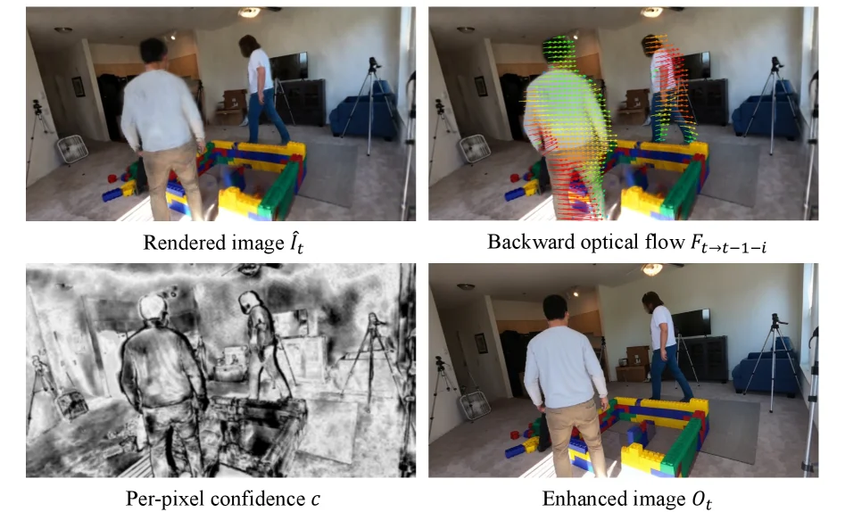
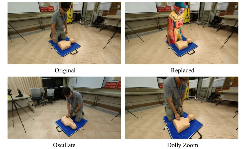
Figure 11. Visualization of motion-adaptive consistency injection (Sec. 3.4 ). From left to right, top to bottom: rendered input, backward optical flow, per-pixel confidence map, and enhanced output. Figure 12. Applications. Top: human replacement with a different identity (right) while keeping the background (left). Bottom: novel trajectory rendering with oscillating motion (left) and dolly zoom (right).

This diagram (Figure 11) illustrates the working principle of the "motion - adaptive consistency injection" module proposed in the paper. This module is a crucial step in the entire 4D human body scene reconstruction process, aiming to improve the quality and consistency of the final synthesized image.

Let's analyze each part of the diagram and the information flow in detail:

1. Top - left: Rendered image (\(\hat{I}_t\))

This image represents the initial rendered image generated by the method at a certain stage or a basic image that needs to be enhanced. It shows an indoor scene with two human body models and some colorful obstacles (similar to building blocks). This image is the input for the subsequent processing steps.

2. Top - right: Backward optical flow (\(F_{t \leftarrow t - 1 - i}\))

This image visualizes the backward optical flow from the time step \(t\) to the earlier time step \(t - 1 - i\). Optical flow is a technique used to describe the motion of pixels in an image sequence. The term "backward" here means that we are concerned with the motion information from the current frame \(t\) back to the previous frames. In the image, the direction and magnitude of the motion of each pixel are represented by colored arrows or vectors. For example, green may represent a smaller motion or a motion in a specific direction, while red may represent a larger motion or a motion in a different direction. These optical flow vectors provide information about how the human body and the background move over time. This optical flow information will be used to guide the subsequent enhancement process to ensure the consistency of motion.

3. Bottom - left: Per - pixel confidence map (\(c\))

This image is a grayscale image, where the brightness or intensity represents the confidence level of the corresponding pixel. The brighter areas indicate that the model has more confidence in the estimation of that area, while the darker areas indicate a lower confidence level. The confidence map is usually used to identify which parts of the image are reliable (for example, clearly visible human body or background) and which parts are uncertain (possibly due to occlusion, low resolution, or motion blur). In this context, it may be used to weight the optical flow information or to decide which areas need more attention or correction during the enhancement process.

4. Bottom - right: Enhanced image (\(O_t\))

This is the final output image obtained after processing by the "motion - adaptive consistency injection" module. Compared with the "rendered input image" in the top - left corner, this image looks clearer, more detailed, or has better motion consistency. The enhancement process combines the rendered input image, the backward optical flow information, and the per - pixel confidence map. Specifically, this method may use the optical flow information to correct motion blur or fill in the missing motion information, and adjust the intensity or method of enhancement according to the confidence map, so as to generate a higher - quality and more consistent image.

Information flow and operation mechanism of the method:

This diagram reveals the specific operation mode of the "motion - adaptive consistency injection" module:

  • Input stage: The method first obtains an initial rendered image \(\hat{I}_t\).
  • Motion analysis stage: Calculate the backward optical flow \(F_{t \leftarrow t - 1 - i}\) from the current frame \(t\) to the previous frames to capture the pixel - level motion information.
  • Confidence assessment stage: Generate a per - pixel confidence map \(c\) to evaluate the reliability of each pixel in the initial rendered image.
  • Enhancement stage: Combine the rendered image, the optical flow information, and the confidence map for "motion - adaptive consistency injection". This process may include:
    • Using the optical flow information to correct or supplement the motion information in the initial rendered image to ensure that the motion of objects (especially the human body) is consistent over time.
    • Using the confidence map to weight the enhancement process. For example, apply less modification in the area with high confidence and more correction or filling in the area with low confidence.
    • This "adaptive" feature means that the method will adjust its processing method according to different parts of the image content (such as the degree of motion, clarity).

In this way, the method can use the temporal correlation between multiple frames of images to improve the quality of a single - frame image, especially in the motion - rich areas and the areas that may be occluded or insufficiently observed. The final output enhanced image \(O_t\) is visually clearer and more consistent than the input rendered image, which shows that the method effectively solves the artifact problem that may occur in 4D reconstruction under the low - overlap camera setup.

In short, this diagram shows how to enhance the initial rendered image by combining the optical flow and confidence information to achieve motion - adaptive consistency injection and improve the quality of 4D human body scene reconstruction.

Figure 11. Visualization of motion-adaptive consistency injection (Sec. 3.4 ). From left to right, top to bottom: rendered input, backward optical flow, per-pixel confidence map, and enhanced output. Figure 12. Applications. Top: human replacement with a different identity (right) while keeping the background (left). Bottom: novel trajectory rendering with oscillating motion (left) and dolly zoom (right).

This figure is from the paper 4D Human - Scene Reconstruction from Low - Overlap Captures and is used to demonstrate the applications of the proposed method, especially the "motion - adaptive consistency injection" - related content and the application effects.

First, look at the four sub - figures, which are "Original", "Replaced", "Oscillate", and "Dolly Zoom".

  1. For the two sub - figures "Original" and "Replaced" (the first row):
  2. "Original" shows the original scene, that is, a person performing an operation (such as CPR demonstration) on a human body model. It presents the original input situation without human replacement processing, and both the background and the character are in their original states.
  3. "Replaced" shows the result after human replacement. The original person is replaced by a clown image, while the background (such as the desks, chairs, whiteboards in the room, etc.) remains unchanged. This reflects the "human replacement" application of the method, which can replace humans of different identities while maintaining the consistency of the background.

  4. For the two sub - figures "Oscillate" and "Dolly Zoom" (the second row):

  5. "Oscillate" shows the result of new trajectory rendering with oscillating motion. The character's action in the figure is in an oscillating form, which is a new motion trajectory generated by the method. It demonstrates the method's ability in "novel trajectory rendering" and can generate motion patterns that did not exist before.
  6. "Dolly Zoom" shows the result of new trajectory rendering with dolly zoom. The character's action shows the effect of dolly zoom, which is also a new motion trajectory generated by the method. It further proves that the method can create a variety of new motion trajectories to meet different application needs.

Overall, this figure intuitively shows the effect of the StudioRecon method proposed in the paper in practical applications through the comparison between the original scene and the scene processed by the method (human replacement, new trajectory rendering). The method decouples the background and humans. First, it enhances the background supervision (synthesizes a large number of camera - controlled new views using a video diffusion model), then robustly initializes the deformable Gaussian humans (cross - view identity association and multi - view keypoint triangulation fitting), and finally coordinates the synthesized output by injecting motion - adaptive consistency through a recursive enhancement module, thus achieving these application effects. In this result figure, we can see: - Comparison objects: "Original" is compared with "Replaced" to show the effect of human replacement; "Oscillate" and "Dolly Zoom" each show the effects of different types of new trajectory rendering. At the same time, they can also be implicitly compared with other original or pre - processed scenes (not shown). - Conclusion: The method can successfully achieve human replacement (replace the character's identity while keeping the background unchanged) and new trajectory rendering (generate new motion trajectories such as oscillating and dolly zoom). It proves the method's ability in 4D human - scene reconstruction, especially its effectiveness in real - world scenarios (low - overlap camera capture), and achieves state - of - the - art new view synthesis effects and supports these applications.

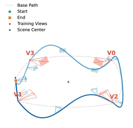
Figure S1. Augmented camera trajectory for iterative refinement. We interpolate between synthesized camera poses while adding sinusoidal height variation and compensating pitch rotation, providing additional supervision from elevated and lowered vantage points.

This figure (Figure S1) illustrates the augmented camera trajectory proposed in the paper, used for iterative refinement. Let's break down the components and their meanings:

  1. Base Path: The dashed line represents the "Base Path." This typically refers to the initial, possibly sparse and low-overlap, camera trajectory. It serves as the foundation for subsequent enhancements.

  2. Start and End Points: The green circle is labeled "Start," and the orange square is labeled "End." These define the beginning and ending positions of the camera trajectory. The camera will move along this path for capturing or synthesizing views.

  3. Training Views: Red circles are marked as "Training Views," labeled V0, V1, V2, V3, etc. These are keyframes where the camera captures or synthesizes images along the trajectory. They provide the observational data needed for reconstruction.

  4. Scene Center: The blue star represents the "Scene Center." This is the geometric center of the scene being reconstructed, around which all camera viewpoints are arranged.

  5. Camera Views: Each "Training View" (e.g., V0, V1, V2, V3) is surrounded by a fan-shaped area, representing the camera's field of view. Different colors of the fans (e.g., the red fan around V1 versus the light-blue fans at other positions) might indicate different processing methods or data sources. For instance, the red fan could represent an enhanced view synthesized via a specific method (like a video diffusion model), while the light-blue fans might represent original low-overlap views.

  6. Trajectory Enhancement Process:

    • Interpolation: The core idea is to interpolate between synthesized camera poses. This means generating new intermediate camera positions between the existing ones on the "Base Path."
    • Sinusoidal Height Variation: During interpolation, the height of the newly generated camera poses varies sinusoidally. This allows the camera to capture the scene from higher or lower positions, providing "elevated" and "lowered" viewpoints, which supplements the potentially missing vertical information in the original low-overlap setup.
    • Compensating Pitch Rotation: As the camera's height changes, its pitch rotation (angle of tilt) is adjusted accordingly. This ensures that even after the height change, the camera's shooting angle remains appropriate for clear scene capture.
  7. Data/Information Flow and Method Operation:

    • Initial Setup: Initially, there is a "Base Path" (dashed line) based on sparse, low-overlap cameras, with "Training Views" (like V0, V2, V3) distributed along it.
    • Trajectory Enhancement: The method then enhances this trajectory by interpolating between existing camera poses and introducing "sinusoidal height variation" and "compensating pitch rotation," generating new camera poses (e.g., the position of V1 and its field of view). These new poses provide additional supervisory information from different heights.
    • Purpose: The purpose of this augmented camera trajectory is to provide more supervisory information, especially from "elevated and lowered vantage points," to improve the quality of 4D human-scene reconstruction. This compensates for the deficiencies of the original low-overlap setup by leveraging more diverse perspectives.

In summary, this figure demonstrates a technique that enhances an initial sparse camera trajectory by intelligently generating additional, more informative camera views through interpolation and adjustments in height and angle. These enhanced views provide more comprehensive supervision for the 4D reconstruction process, helping to improve accuracy and completeness, particularly in areas poorly covered by the original data.

This figure is part of the methodology, showing how to construct an augmented camera trajectory for iterative optimization, rather than being a final result figure. It illustrates how data (camera views) is processed and enhanced using specific algorithms (interpolation, height and angle adjustments).

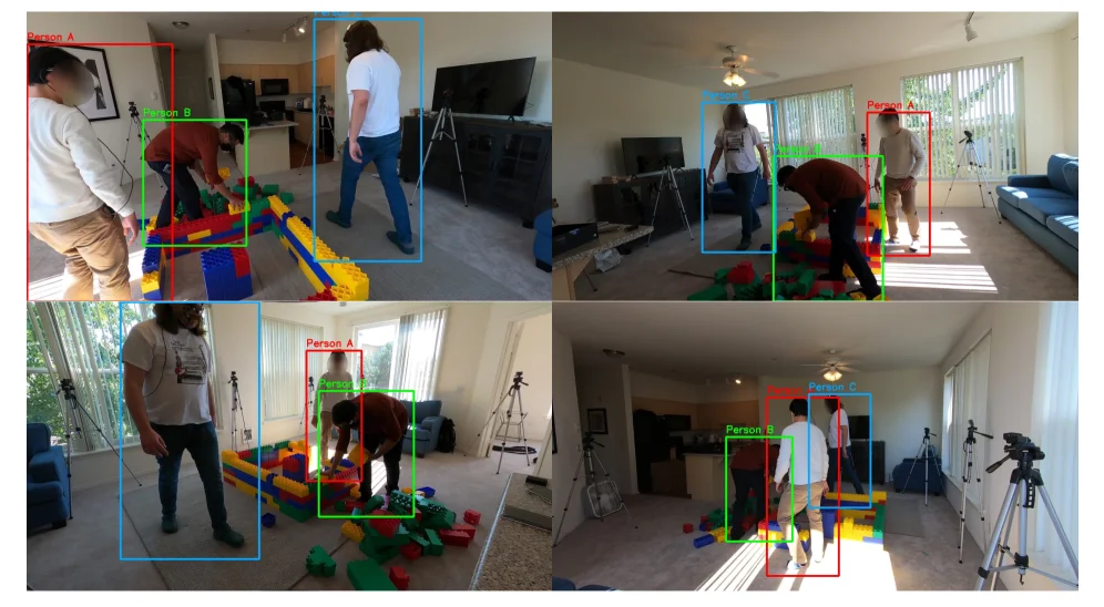
Figure S2. Cross-view identity association. Each color represents the same person matched across 4 cameras with low overlap. Our method achieves 97.8% association accuracy across all 8 scenes from EgoHumans, Harmony4D, Mobile Stage, and SelfCap (Table 3 ).

This figure (Figure S2) primarily illustrates the achievement of the "cross-view identity association" method proposed in the paper. It visualizes the tracking and identification of multiple people in the same scene across four different camera viewpoints, representing a low-overlap capture setup.

First, let's understand the structure of the image: * Overall Layout: The image is composed of four independent sub-figures arranged in a 2x2 grid. Each sub-figure represents a different camera viewpoint capturing the same dynamic scene (people playing with building blocks). These cameras have limited overlap in their fields of view, which is the "low-overlap" challenge the paper aims to address. * Color Coding: The key to understanding the figure lies in the color coding. According to the caption, each color represents the same person, matched across different camera viewpoints. For example, the red box always represents "Person A," the green box represents "Person B," and the blue box represents "Person C" (if present). This color consistency is a visual representation of "identity association."

Next, we analyze each sub-figure to understand how the method works: 1. Top-Left Sub-figure: This viewpoint shows three people. The red box marks "Person A," standing on the left, wearing a light-colored top and khaki pants. The green box marks "Person B," bending over and interacting with the blocks, wearing a brown top and dark pants. The blue box marks "Person C," standing further away, wearing a white T-shirt and blue jeans. This sub-figure shows the initial viewpoint and the distribution of people. 2. Top-Right Sub-figure: This is a different camera viewpoint, possibly from a greater distance or a different angle. Here, we can still see "Person A" (red box), "Person B" (green box), and "Person C" (blue box). Although their relative positions and sizes within the frame have changed, the color coding remains consistent, indicating that the method correctly identifies these individuals across different viewpoints. For instance, "Person A" is on the right in this sub-figure, while "Person B" is in the middle-right, bending over. 3. Bottom-Left Sub-figure: This viewpoint is closer to the block area. Here, "Person A" (red box) stands on the left, wearing a light-colored T-shirt and dark pants. "Person B" (green box) is bending over, interacting with the blocks, wearing a brown top. "Person C" does not appear in this viewpoint, or is not in the main focus of the current frame. 4. Bottom-Right Sub-figure: This viewpoint again shows "Person A" (red box), "Person B" (green box), and "Person C" (blue box). They are standing near the block pile, with positions and poses different from the previous viewpoints. The color coding remains accurate, proving the robustness of the identity association.

Revealing How the Method Works: While this figure is a result demonstration, it indirectly illustrates the core ideas of the method: * Challenge of Identity Association: In low-overlap camera views, accurately matching the same person across different viewpoints is very difficult due to factors like perspective differences, occlusions, and changes in human pose. * Solution by the Method: The proposed StudioRecon method in the paper uses a mechanism (specific details are described in the paper, such as "cross-view identity association" and "triangulated multi-view keypoint fitting" mentioned in the caption) to achieve this. This figure demonstrates the successful application of this mechanism: regardless of changes in position, pose, or viewpoint, the same person is consistently assigned the same color (i.e., the same identity label). * Data Flow: Although the figure does not directly show data flow, it can be inferred that the input is video sequences from multiple low-overlap cameras. The method processes these sequences, performs feature extraction, matching, and tracking, and ultimately outputs the person detection results with correct identity labels, as shown in the figure.

Conclusion: This figure clearly demonstrates the effectiveness of the paper's method in cross-view identity association. By achieving a 97.8% association accuracy across all 8 scenes from the EgoHumans, Harmony4D, Mobile Stage, and SelfCap datasets (as stated in Table 3, referenced in the caption but not visible in the image), it proves that the method can accurately identify and track multiple people in low-overlap camera setups. The color coding in the figure intuitively showcases this achievement, allowing readers to immediately understand the method's performance.

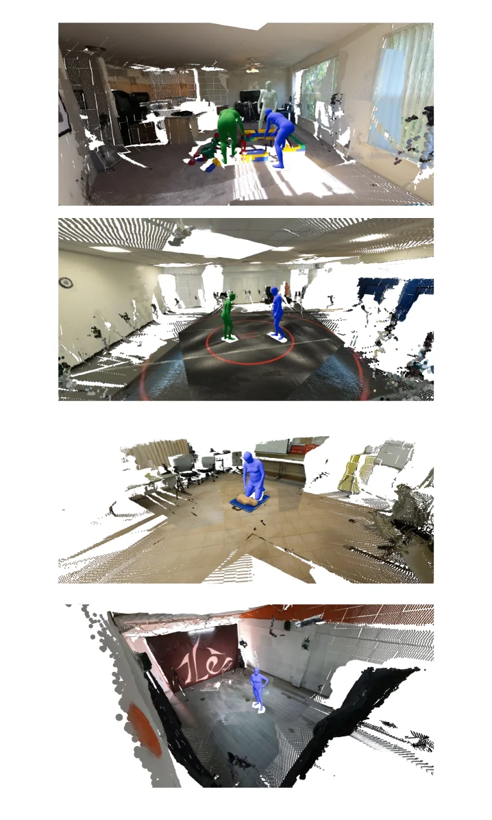
Figure S3. Initialized human pose visualization across four scenes. Point clouds are rendered with overlaid SMPL meshes, demonstrating accurate body pose estimation from sparse multi-view inputs.

This figure (Figure S3) visualizes the initialized human pose estimation results of our proposed StudioRecon method across four different scenes. It consists of four separate sub-figures, each representing a distinct real-world scene, arranged vertically from top to bottom. Together, these sub-figures demonstrate how our method accurately estimates human pose from sparse, low-overlap camera inputs.

Key components and information flow in each sub-figure: 1. Point Cloud Background: The background of each sub-figure is a point-cloud representation of the indoor scene, reconstructed from sparse multi-view inputs. These point clouds appear incomplete and fragmented, reflecting the "low-overlap" camera limitation where not all scene areas are sufficiently observed. The color and density variations in the point clouds illustrate the scene's structure and objects, though details might be unclear. 2. SMPL Meshes: Overlaid on the point-cloud background are human-shaped meshes in green or blue. These meshes are obtained by fitting the SMPL (Skinned Multi-Person Linear) model, representing the initialized human poses. SMPL is a common parametric human model capable of effectively representing human shape and pose. * Color Differentiation: Different individuals are represented by different colors (e.g., green and blue), or it might be used to distinguish different stages or views of a single individual. * Pose Accuracy: These SMPL meshes accurately cover the actual position and pose of the people in the scene. For example, in the first sub-figure, two figures (one green, one blue) are visible in different action states (one appears to be bending, the other standing). In the second sub-figure, two figures stand within a circular area, their poses accurately represented by the corresponding SMPL meshes. 3. Method Operation and Data Flow: * Input: Although not directly shown in the figure, the input, according to the caption and paper context, is sparse image sequences from multiple low-overlap cameras. * Processing Pipeline: Our method first robustly initializes deformable Gaussian human models through cross-view identity association and triangulation of multi-view keypoints from these sparse multi-view inputs. These initialized human poses are then visualized on the corresponding scene point clouds. * Output: The figure displays the output of this initialization process—accurate human pose estimation, visualized as SMPL meshes overlaid on the scene point clouds. 4. Conclusion: This figure, through examples from four different scenes, intuitively proves that our method can accurately estimate human pose from sparse multi-view inputs. The SMPL meshes closely align with the actual position and pose of the people in the scenes, indicating the method's effectiveness and accuracy. This lays a solid foundation for subsequent 4D reconstruction and enhancement steps.

In summary, this figure effectively illustrates the accuracy and robustness of our method in initializing human poses by showing the results of accurately estimated SMPL human pose meshes overlaid on point-cloud backgrounds reconstructed from sparse multi-view inputs in real-world scenes, even under the challenging conditions of low-overlap cameras.

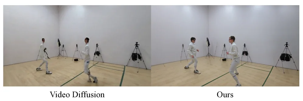
Figure S4. Video diffusion models (Ren et al. , 2025 ) produce geometrically inconsistent humans (left), while our explicit reconstruction maintains accurate body shape (right).

This figure presents a direct visual comparison to illustrate the performance difference between existing video diffusion models and the method proposed in this paper for dynamic human reconstruction.

First, let's analyze the two main sections of the image, labeled "Video Diffusion" (left) and "Ours" (right).

  1. Left Section: "Video Diffusion"

    • Content: This part shows the reconstructed dynamic human scene using a video diffusion model (e.g., the work by Ren et al., 2025).
    • Observations: The image depicts two individuals in white fencing attire engaged in an activity within an indoor space. The background consists of light-colored walls and a wooden floor, with some tripods and equipment, possibly cameras or other capture devices, visible.
    • Problem Revealed: According to the original figure caption, the main issue with this approach is that it "produces geometrically inconsistent humans." Visually, one can observe that the poses and shapes of the figures on the left appear somewhat unnatural or incoherent. For instance, the leg posture of the left figure or the overall silhouette of the right figure might seem distorted or not conforming to physical laws. This indicates that video diffusion models may struggle to maintain the structural consistency and accuracy of human figures during motion.
  2. Right Section: "Ours"

    • Content: This part shows the same scene reconstructed using the method proposed in this paper (labeled "Ours," meaning our method).
    • Observations: Similarly, it shows two individuals in white fencing attire in the same indoor setting. The background and foreground elements are largely consistent with the left part.
    • Advantage Demonstrated: According to the original figure caption, the characteristic of this approach is that it "maintains accurate body shape." Visually, the poses and shapes of the figures on the right appear more natural and accurate. For example, the proportions and positions of the legs, torso, and arms of the figures seem to conform better to the structure of a real human body. This suggests that the proposed method better handles the geometric consistency of human motion, thus generating more accurate human reconstruction results.
  3. Comparison and Conclusion:

    • Comparative Objects: The figure directly compares the output of the video diffusion model (left) with the output of the proposed method (right).
    • Data or Information Flow: The intention of the figure is to allow readers to understand the performance differences between the two methods when processing the same or similar scenes through visual comparison. The information flow is from observing the shortcomings of the left model to observing the improvements of the right model, thereby drawing a conclusion.
    • Coordinates and Scene: Although there are no explicit coordinate axes, it can be inferred that this is a typical indoor motion capture scene. The elements in the scene (e.g., figures, background equipment) are corresponding in both parts, facilitating a direct comparison.
    • Conclusion: This figure clearly reveals that the proposed method in this paper outperforms the video diffusion model in terms of maintaining geometric consistency in human reconstruction. Specifically, the proposed method addresses the issue of geometric inconsistency in human reconstruction that arises with video diffusion models, thus generating more accurate and natural dynamic human models. This supports the point made in the paper's abstract that the proposed method (StudioRecon), by decoupling background and humans and employing other techniques (such as enhancing background supervision by synthesizing hundreds of camera-controlled novel views with a video diffusion model, and robustly initializing deformable Gaussian humans with cross-view identity association and triangulated multi-view keypoint fitting), can achieve higher-quality 4D human scene reconstruction.

In summary, this figure, through visual comparison, intuitively demonstrates the significant advantage of the proposed method in this paper over video diffusion models in maintaining geometric consistency during dynamic human reconstruction.

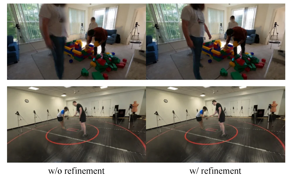
Figure S5. Effect of multi-view pose refinement. Without refinement (left), inaccurate SMPL poses cause blurry or semi-transparent body parts. With refinement (right), poses are corrected via cross-view triangulation, producing a sharper human reconstruction.

This figure (Figure S5) illustrates the role of multi - view pose refinement in 4D human - scene reconstruction. By comparing the results of "without refinement (w/o refinement)" and "with refinement (w/ refinement)", it clearly shows the operation logic and performance improvement of the method.

Components of the Figure and Information Flow

  • Layout Structure: The figure is divided into two groups, and each group contains two sub - figures, corresponding to the situations of "without refinement" (left) and "with refinement" (right) respectively. The upper - group scene is an indoor environment with building blocks and people, and the lower - group is an indoor environment with two people interacting (with a red circle - marked area).
  • Comparison Objects: The left figure (labeled "w/o refinement") and the right figure (labeled "w/ refinement") in each group are the results of human reconstruction in the same scene and the same action at different processing stages, which are used to compare the differences before and after pose refinement.
  • Information Flow Logic: From left to right, it shows the change process from "human reconstruction without pose optimization" to "human reconstruction with pose optimization". The core is to compare the impact of pose optimization on the reconstruction quality.

Operation Mode of the Method (Revealed from the Figure)

  1. Problem Background (Without Refinement): In the sub - figures of "w/o refinement" (such as the left figures in the two groups), due to the inaccuracy of human pose estimation (such as SMPL model fitting) from monocular or multi - views, some parts of the human body will be blurred, semi - transparent or have shape distortion. This is because under the condition of low - overlap cameras, the pose estimation from a single perspective is prone to errors, and there is a lack of consistency constraints from multi - views, which leads to the geometric inconsistency of the human body model (such as limb twisting and partial missing).
  2. Optimization Method (Pose Refinement): The sub - figures of "w/ refinement" (such as the right figures in the two groups) show the role of cross - view triangulation. This method corrects the inaccurate SMPL pose by combining the views of multiple low - overlap cameras and using the principle of triangulation (calculating the accurate pose of the human body in 3D space from the 2D keypoints observed from different perspectives of camera positions).
  3. Effect Manifestation: After optimization, the human reconstruction result is clearer and more accurate. For example, in the right figures of the two groups, the shape of the human limbs (such as arms and legs) is more complete, and there is no blurring or semi - transparency, which shows that pose optimization solves the reconstruction quality problem caused by inaccurate pose estimation under low - overlap cameras.

Details of the Result Figure (Coordinates, Comparison and Conclusion)

  • Coordinates and Scenes: There are no explicit coordinate labels in the figure, but the scenes are real indoor environments (the upper group is a building - block scene, and the lower group is an interactive scene). The position of the person in the scene is relatively fixed, which is convenient for comparing the reconstruction effects at the same position.
  • Comparison Objects: The left (without refinement) and right (with refinement) sub - figures in each group are the direct comparison objects. The variable is "whether multi - view pose optimization is performed", and other factors (such as scene, human action, and camera setting) remain the same.
  • Conclusion: Through comparison, it can be concluded that multi - view pose optimization (especially cross - view triangulation) can significantly improve the quality of human reconstruction under low - overlap cameras, solve the problems of blurring, semi - transparency or geometric inconsistency caused by inaccurate pose estimation, and make the reconstructed human body clearer and more in line with the real form. This also verifies the effectiveness of the link of "correcting the pose through cross - view triangulation" in the StudioRecon method proposed in the paper.

Figure S6. Effect of mask dilation. Without dilation (left), insufficiently masked human regions at t = 0 t{=}0 are baked into the static background Gaussians, leaving ghosting artifacts as humans move. With 21px dilation (right), the background is cleanly separated.

This figure (Figure S6) illustrates the critical role of mask dilation in separating dynamic humans from static backgrounds, visually demonstrating how the method avoids ghosting artifacts and achieves clean background separation through a comparison between "without dilation (w/o dilation)" and "with dilation (w/ dilation)" scenarios.

Explanation of the Figure's Structure and Components:

  • Overall Layout: The figure is divided into two main parts (top and bottom), each containing two subfigures corresponding to the "without dilation" (left) and "with dilation" (right) cases. The top scene is an indoor environment (with Lego blocks, a TV, and interacting people), while the bottom scene is another indoor setting (with red-blue mats and moving people).
  • Subfigure Comparison:
  • Left Column (w/o dilation): Represents the case without mask dilation. In these subfigures, the yellow-boxed regions show ghosting artifacts when humans move. For example, in the left subfigure of the top part, the moving person’s leg area leaves a blurry residue in the background; in the left subfigure of the bottom part, the moving person’s foot area also has similar ghosting.
  • Right Column (w/ dilation): Represents the case with 21px dilation. The yellow-boxed regions show that after dilation, the background becomes clean, and ghosting artifacts disappear. When humans move, the background no longer retains blurry images of the human body, achieving a clear separation between the background and the dynamic human.
  • Data/Information Flow: The "flow" here refers to the result comparison of the processing pipeline. First, the method needs to generate a mask for the scene to distinguish between humans and the background. When the mask is not dilated (left column), some human regions (especially at the edges or during motion) may not be fully masked, causing these regions to be incorrectly "baked" into the static background’s Gaussian model. When the human moves, the residual background information conflicts with the current human position, forming ghosting. With mask dilation (right column), the mask’s range is expanded (21 pixels), ensuring that human regions (including those during motion) are fully excluded from the background modeling. Thus, in subsequent reconstruction, the background remains static and clean, even when the human moves, without artifacts.

How the Method Works (Inferred from the Figure):

This figure reveals the key step of separating the background and humans in the method:
1. Mask Generation and Dilation: First, a human mask is generated for each time frame (e.g., t=0 in the figure) to identify human regions. To ensure accurate background modeling, the human mask is dilated (e.g., by 21 pixels). The purpose of dilation is to expand the mask’s range to cover the human body’s edge regions (especially blurred or undetected areas during motion), preventing these regions from being incorrectly included in the background model.
2. Background Modeling: During the background modeling phase (e.g., when synthesizing new views using a video diffusion model or initializing Gaussian models), the dilated mask ensures that background regions (non-human areas) are correctly modeled. Thus, when the human moves, the background model does not contain residual human information, avoiding ghosting artifacts.
3. Result Validation: By comparing the "without dilation" and "with dilation" results, the figure shows how dilation effectively separates the background and dynamic humans. Without dilation, the background has ghosting (residue from human motion); with dilation, the background is clean, and no artifacts appear when the human moves. This verifies the importance of mask dilation in 4D human-scene reconstruction from sparse, low-overlap camera captures, especially in sparse camera settings where dense and accurate background separation is critical.

Details of the Result Figure:

  • Coordinates/Regions: The yellow boxes mark the regions to focus on, i.e., areas prone to ghosting when humans move. In the top part, the yellow box is near the person’s legs and Lego blocks; in the bottom part, it is near the moving person’s feet.
  • Comparison Objects: The comparison is between the background separation effects of "without dilation (w/o dilation)" and "with dilation (w/ dilation)" (21 pixels). The left column is the undilated case, and the right column is the dilated case.
  • Conclusion: From the figure, we conclude that mask dilation (especially 21 pixels) effectively separates the background and dynamic humans, avoiding ghosting artifacts. This is crucial for 4D human-scene reconstruction from sparse, low-overlap camera captures, as it ensures the accuracy of the background model, thus improving the overall reconstruction quality (e.g., for novel view synthesis, trajectory rendering, etc.).

Figure S7. Limitations of our method. Comparing ground truth (left) with our reconstruction (right), dynamic objects held by actors are not reconstructed because they lie outside the SMPL body model.

This figure (Figure S7) illustrates a limitation of our method. It demonstrates, by comparing the "ground truth" (left image) with the "reconstruction result" of our method (right image), that when dynamic objects are outside the scope of the SMPL human body model, these objects cannot be reconstructed by our method.

Let's analyze this figure in detail:

  1. Image Layout and Comparison Objects:

    • The entire figure is divided into two sets of comparisons (top and bottom), each containing left and right sub-images. The left sub-image represents the "ground truth" (actual scene captured), while the right sub-image shows the "reconstruction" result from our method.
    • The top scene is a basketball court, and the bottom scene is a fencing training room.
  2. Top Section (Basketball Court Scene):

    • Left (Ground Truth): We can see a person wearing red shorts standing on the basketball court, shooting a basketball. The basketball (a brown sphere) is in mid-air, flying towards the hoop. Both the hoop and the basketball are clearly captured.
    • Right (Reconstruction Result): In this scene, the person and the hoop are reconstructed, but the basketball in mid-air is missing. This is because the basketball is a dynamic object, and its position and movement are outside the defined scope of the SMPL human body model. Our method primarily focuses on reconstructing the human body model, and thus cannot accurately capture and reconstruct dynamic objects (like the basketball) that fall outside this model.
    • Yellow Boxes: Yellow boxes are used to highlight the key areas for comparison. In the top section, the yellow boxes highlight the hoop and basketball (left image) and the hoop (right image), emphasizing the absence of the basketball in the reconstruction result.
  3. Bottom Section (Fencing Scene):

    • Left (Ground Truth): Here, two people are wearing fencing gear and engaged in a fencing action. One person is holding a sword (a black, slender object). This sword is part of their action and is also a dynamic object.
    • Right (Reconstruction Result): In this scene, the two people are reconstructed, but the swords they were holding are missing. The reason is similar to the basketball case: the sword, as a dynamic object, its position and form are outside the scope of the SMPL human body model, and therefore cannot be reconstructed by our method.
    • Yellow Boxes: Yellow boxes again highlight the key areas for comparison. In the bottom section, the yellow boxes highlight the sword held by the fencer (left image) and the original position where the sword was held by the fencer (right image), emphasizing the absence of the sword in the reconstruction result.
  4. Revealing Method Limitations (Through This Figure):

    • This figure reveals an important limitation of our method: it relies on the SMPL human body model to represent the human body. When dynamic objects (like the basketball or sword) have movements or positions outside the representation range of this model, these objects cannot be effectively reconstructed.
    • Although our method may perform well in handling the human body itself and the background, its reconstruction capability is limited for dynamic attachments or independent dynamic objects that fall outside the SMPL model's scope.
  5. Conclusion:

    • The figure clearly shows that when dynamic objects (like the basketball or sword) are outside the representation range of the SMPL human body model, our method cannot reconstruct these objects. This results in the absence of these objects in the reconstruction result, as shown by the left-right comparisons. This is a known limitation of our method.

Figure S8. Shadow artifacts. Shadows baked into the static background at t = 0 t{=}0 (left) remain fixed and do not follow human motion at later timesteps (right).

This figure (Figure S8) from the paper "4D Human-Scene Reconstruction from Low-Overlap Captures" visually demonstrates a key issue: shadows baked into the static background at time t=0 do not update to follow human motion at later timesteps.

First, let's analyze the components in the image:

  1. Overall Layout: The image is divided into two main sections, labeled "timestep 0" (left) and "timestep 60" (right). This indicates the state of the scene at two different time points.
  2. Timestep 0 (Left Section):
    • This part shows the scene at the initial time point (t=0).
    • We can see an indoor environment with windows, tripods with cameras, a blue sofa, and some colorful block structures.
    • There are several people in the scene; one person (wearing a light-colored top and khaki pants) is bending over, interacting with the blocks.
    • Key Point: At this time point, there are visible shadows on the floor, particularly around the person and near the block structures. These shadows are a result of the lighting conditions and object positions at that time and have been "baked" into the static background.
  3. Timestep 60 (Right Section):
    • This part shows the same scene at a later time point (t=60).
    • Notice that the person's position and posture have changed: the person who was previously bending over is now standing upright, and their position has also shifted.
    • Key Point: Despite the change in the person's position and posture, the shadows that were present on the floor at timestep 0 (as shown within the yellow boxes) have not moved or updated. These shadows remain fixed in their original positions and do not match the new person posture.

Data/Information Flow and Method Revealed:

This image does not show the flow of a method but rather illustrates a problem that might arise with existing methods or simple processing approaches when reconstructing 4D human-scene data. Specifically:

  • Problem Illustration: When attempting to reconstruct a 4D human-scene from sparse, low-overlap camera captures, if the background (including shadows) is statically baked, these shadows will not correctly reflect new lighting conditions as the person moves. This leads to visual inconsistencies, i.e., shadow artifacts.
  • Implicit Method Requirement: The image suggests that an effective 4D reconstruction method needs to handle dynamically changing shadows. Ideally, shadows in the background should update in real-time according to the person's movement and changes in environmental lighting.
  • Connection to the Paper's Method: Although the image does not directly show how the proposed StudioRecon method solves this problem, it highlights the severity of the issue. Techniques mentioned in the paper, such as using a video diffusion model to synthesize new camera views for enhanced background supervision, and a recursive enhancement module that injects motion-adaptive consistency, aim, in part, to avoid such shadow artifacts and ensure visual consistency in the reconstructed scene across different timesteps.

Coordinates, Comparison Objects, and Conclusion:

  • Coordinates/Time Points: The comparison occurs between two distinct time points: timestep 0 and timestep 60.
  • Comparison Objects: The objects of comparison are the visual representations of the same scene at different time points, specifically focusing on the shadows on the floor relative to the person's position.
  • Conclusion: The image clearly demonstrates that if shadows baked into the static background are not correctly updated to match the person's motion, shadow artifacts will appear. Specifically, shadows baked into the background at timestep 0 remain fixed in their original locations at timestep 60, even though the person has moved. This proves the importance of handling dynamic shadows in scene reconstruction, which is a key challenge the paper's method aims to address.
← → flip · ↑ ↓ scroll notes · Esc exit