🌊 Tide

Information moves like the tide. We pick the waves worth studying.

中文

← Today's tide

Published 2025-03-25 · Central South University, Great Bay University, The University of Liverpool · Feiyang Wang, Xiaomin Yu, Wangyu Wu

CubeRobot: Grounding Language in Rubik's Cube Manipulation via Vision-Language Model

arXiv

Abstract (verbatim)

Proving Rubik's Cube theorems at the high level represents a notable milestone in human-level spatial imagination and logic thinking and reasoning. Traditional Rubik's Cube robots, relying on complex vision systems and fixed algorithms, often struggle to adapt to complex and dynamic scenarios. To overcome this limitation, we introduce CubeRobot, a novel vision-language model (VLM) tailored for solving 3x3 Rubik's Cubes, empowering embodied agents with multimodal understanding and execution capabilities. We used the CubeCoT image dataset, which contains multiple-level tasks (43 subtasks in total) that humans are unable to handle, encompassing various cube states. We incorporate a dual-loop VisionCoT architecture and Memory Stream, a paradigm for extracting task-related features from VLM-generated planning queries, thus enabling CubeRobot to independent planning, decision-making, reflection and separate management of high- and low-level Rubik's Cube tasks. Furthermore, in low-level Rubik's Cube restoration tasks, CubeRobot achieved a high accuracy rate of 100%, similar to 100% in medium-level tasks, and achieved an accuracy rate of 80% in high-level tasks.

Background

Background Analysis

Recent advances in vision-language models (VLMs) have demonstrated remarkable performance in natural language processing tasks, such as text comprehension and image captioning. However, applying these technologies to more complex real-world scenarios—like solving Rubik’s Cubes—remains challenging. As a 3D spatial puzzle, the Rubik’s Cube tests not only an algorithm’s spatial reasoning but also its ability to handle dynamic environmental changes. Traditional robots rely on fixed algorithms and complex vision systems, struggling to adapt to unexpected cube states (e.g., partially scrambled cubes). Thus, enabling machines to flexibly understand and solve such problems like humans is a critical research goal.

Previous methods face two main limitations: first, existing multimodal models (e.g., LLaVA, Flamingo) excel at language and image processing but underperform in 3D tasks like depth perception and object relationship modeling. Second, even with long-chain reasoning capabilities, these models cannot independently solve high-difficulty cube restoration tasks. For instance, while humans solve cubes through logical step-by-step reasoning, machines often require preprogrammed algorithms, lacking flexibility.

To address these issues, this paper introduces CubeRobot, a VLM specifically designed for 3×3 Rubik’s Cube solving. Its core idea combines VLM’s multimodal understanding with a specialized dataset (CubeCoT), which includes complex tasks (43 subtasks) that are challenging for humans. Additionally, CubeRobot employs a “dual-loop architecture” and “Memory Stream”: the former processes tasks hierarchically via inner and outer loops, while the latter records natural language descriptions and timestamps to optimize decision-making.

Compared to prior work, this paper’s key differences lie in: 1) focusing on a specific but representative 3D task (Rubik’s Cube) rather than general multimodal problems; 2) improving adaptability in dynamic scenarios through a customized dataset and hierarchical architecture; 3) introducing a memory stream mechanism to enable autonomous reflection and strategy adjustment. This approach not only achieves high accuracy (e.g., 100% for low/medium difficulty tasks) but also provides a new paradigm for solving complex spatial problems.
Method, Figure by Figure

M E T H O D1 / 4

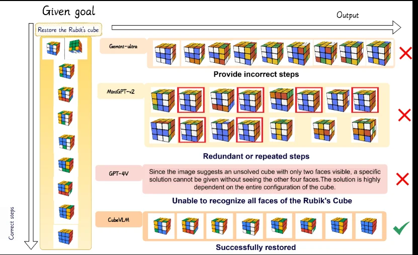
Figure 1. Comparison of Rubik’s Cube Solving Performance.

This figure (Figure 1: Comparison of Rubik’s Cube Solving Performance) clearly illustrates the performance comparison of different models in solving a Rubik's cube task, thereby highlighting the superiority of the CubeRobot method proposed in the paper.

First, let's analyze the overall structure and information flow of the figure: - The left side represents the "Given goal" area. At the top is the task description: "Restore the Rubik's cube." Below it is a vertically arranged sequence of Rubik's cube states, showing the process from a scrambled cube (the second cube from the top) to a completely ordered state (the first cube at the bottom). This sequence represents the "Correct steps," the desired path to solve the Rubik's cube problem. A downward arrow labeled "Correct steps" indicates the order of this restoration process.

  • The right side is the "Output" area, showing the results of different models attempting to solve the Rubik's cube task. These models include Gemini-ultra, MiniGPT-4v, GPT-4V, and CubeVLM. The results for each model are presented as a row or multiple rows of Rubik's cube images, accompanied by brief text descriptions of their performance.

Next, we analyze the performance of each model:

  1. Gemini-ultra:

    • Its output is a row of Rubik's cube images, showing the model's problem-solving steps from left to right.
    • The text description is "Provide incorrect steps."
    • A red "X" is the conclusion, indicating that this model failed to solve the Rubik's cube because it took incorrect steps during the process.
  2. MiniGPT-4v:

    • Its output consists of two rows of Rubik's cube images.
    • The text description is "Redundant or repeated steps."
    • Some Rubik's cube images are highlighted with red boxes, possibly indicating these steps were ineffective, duplicated, or unnecessary.
    • The conclusion is also a red "X," indicating this model also failed to solve the Rubik's cube, as it fell into redundant or repeated operations.
  3. GPT-4V:

    • Its output is not an image of the cube but a text description.
    • The text reads: "Since the image suggests an unsolved cube with only two faces visible, a specific solution cannot be given without seeing the other four faces. The solution is highly dependent on the entire configuration of the cube."
    • The conclusion is a red "X," categorized as "Unable to recognize all faces of the Rubik's Cube." This indicates that the model had difficulty handling a Rubik's cube that was only partially visible and could not plan or solve it effectively.
  4. CubeVLM (the method proposed in the paper):

    • Its output is a row of Rubik's cube images, showing the model's problem-solving steps from left to right.
    • The text description is "Successfully restored."
    • The conclusion is a green checkmark (✓), indicating that this model successfully restored the Rubik's cube by following the correct sequence of steps.

Summarizing what this figure reveals about how the method works: This figure demonstrates the effectiveness of the CubeRobot method (i.e., CubeVLM) through comparison. It shows that, compared to traditional language models (such as Gemini-ultra, MiniGPT-4v, and GPT-4V), CubeVLM can: - Understand the overall configuration of the Rubik's cube, even when only partial faces are visible. - Plan and execute a correct sequence of non-redundant steps. - Ultimately succeed in completing the Rubik's cube restoration task.

The information flow in the figure starts from the "Given goal" on the left (a Rubik's cube problem to be solved), progresses through the "Output" of different models (their problem-solving attempts), and finally shows which models succeed (CubeVLM) and which fail (other models). As a result figure, it visually compares the outcomes (correct cube sequence vs. incorrect steps or inability to solve) and uses clear labels (e.g., "Successfully restored," "Provide incorrect steps") to convey that CubeRobot achieves a high accuracy rate in low-level Rubik's cube restoration tasks (e.g., 100% success as implied by the context and the paper's abstract).

Specific coordinates or numerical values (like accuracy percentages) are not explicitly shown in the figure, but based on the context and the paper's abstract, it can be inferred that CubeVLM performs excellently in this task. The comparison objects are four different models or methods, and the conclusion is that CubeVLM outperforms the other comparison models in the Rubik's cube restoration task.

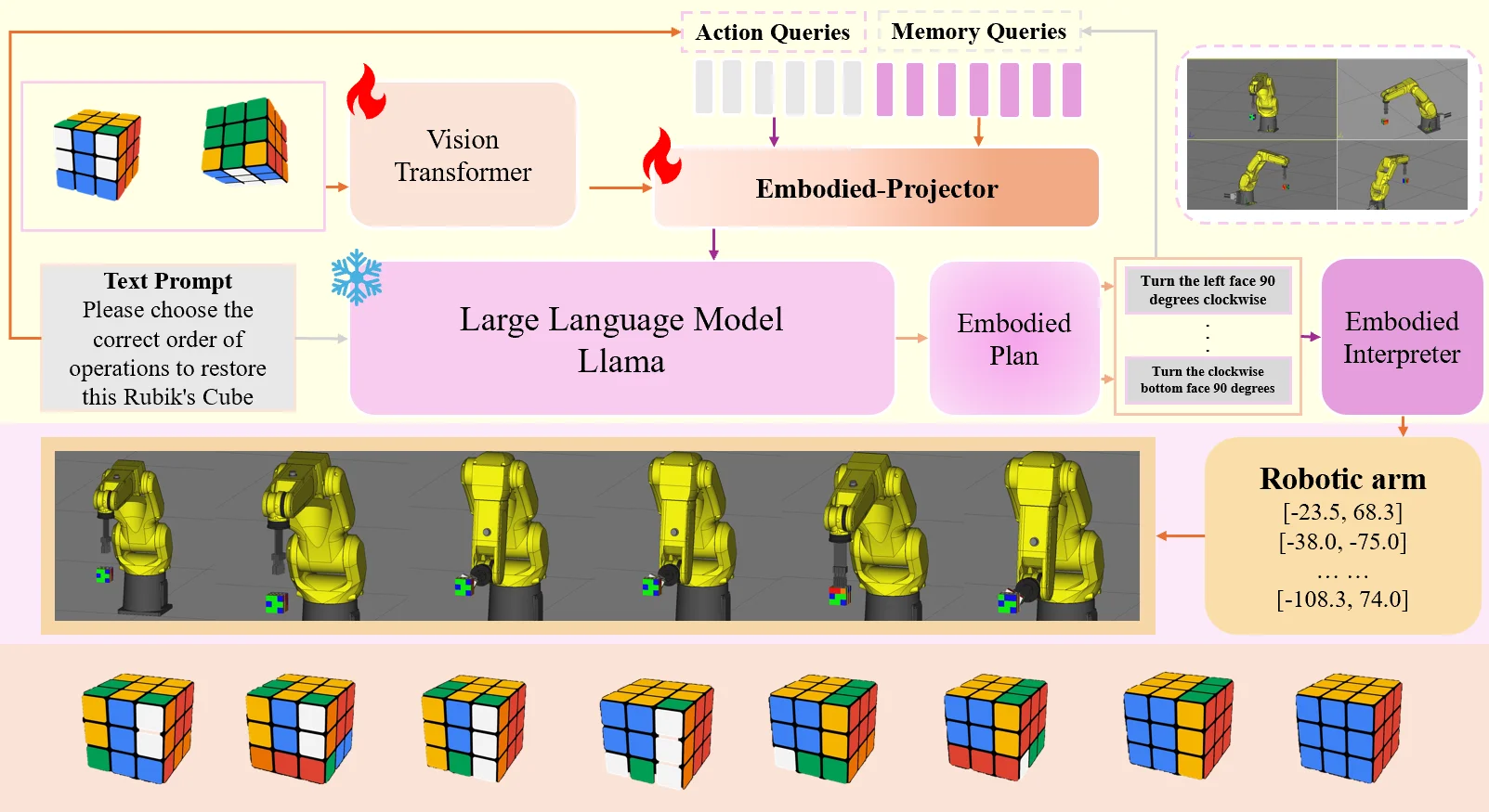
Figure 2. Framework of CubeRobot. The orange arrow shows the vision-language planning process, while the gray arrow represents that we leverage the queried language plans for better policy learning in Rubik’s Cube Manipulation tasks.

This figure illustrates the framework of CubeRobot, a vision-language model designed for solving 3x3 Rubik's Cubes, aiming to endow embodied agents with multimodal understanding and execution capabilities.

First, let's look at the visual processing part at the top. The input on the left consists of two images of a Rubik's Cube in different states, which are fed into a module labeled "Vision Transformer." This module is responsible for processing the image data and extracting features. The output from the "Vision Transformer" points to a module called "Embodied-Projector," along with two types of queries: "Action Queries" (gray bars) and "Memory Queries" (purple bars). These queries, along with the visual features, are processed within the "Embodied-Projector," a process indicated by the orange arrows, corresponding to the "vision-language planning process" in the figure caption.

Next, we examine the language processing part on the left-middle. There is a "Text Prompt" box with the content "Please choose the correct order of operations to restore this Rubik's Cube." This text prompt is sent to a module named "Large Language Model Llama." This large language model is responsible for generating a plan based on the text prompt and visual information.

The output of the "Large Language Model Llama" is an "Embodied Plan," which is presented as a series of specific operation instructions, such as "Turn the left face 90 degrees clockwise," etc. These instructions are then sent to the "Embodied Interpreter."

The output of the "Embodied Interpreter" is the specific parameters to control the robotic arm, such as the coordinate values shown in the "Robotic arm" box (e.g., [-23.5, 68.3], [-38.0, -75.0], etc.). These parameters directly control the movement of the yellow robotic arm displayed at the bottom.

After executing these instructions, the robotic arm causes changes in the state of the Rubik's Cube, as shown in the sequence of images of the Rubik's Cube at the bottom, which gradually change from an initial scrambled state to a solved state.

The figure also includes some feedback loops. For example, there is an arrow from the "Robotic arm" part back to the "Memory Queries" input, indicating that the execution results of the robot might be used to update or optimize the memory queries, thereby improving future planning. Additionally, the figure caption mentions that the gray arrows represent "we leverage the queried language plans for better policy learning in Rubik’s Cube Manipulation tasks," suggesting that the entire system learns and optimizes its planning capabilities through actual operations.

In summary, the workflow of CubeRobot is as follows: first, the Rubik's Cube images are processed by the Vision Transformer, and simultaneously, a plan to restore the Rubik's Cube is generated by combining the text prompt and the language model. Then, this plan is interpreted into specific robot control instructions, which are executed by the robotic arm, thus changing the state of the Rubik's Cube. The system also includes feedback mechanisms that utilize the execution results to optimize future planning and learning.

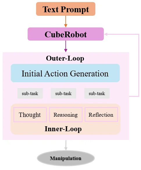
Figure 3. Dual-loop CoT. The outer-loop manages high-level tasks, including initial action planning and iterative refinements, while tracking task progress. The inner-loop executes specific sub-tasks assigned by the outer-loop, employing thought, reasoning, and reflection.

This figure illustrates the Dual - loop Chain - of - Thought (CoT) architecture in the CubeRobot method, clearly presenting the complete process from text prompt to Rubik's cube manipulation (Manipulation) and the collaborative mode of high - and low - level tasks:

1. Input and Initial Trigger

  • Text Prompt: As the starting point of the whole process, it is represented by an orange rectangle. It provides a task description or goal related to Rubik's cube manipulation (for example, "solve the Rubik's cube", "perform a specific Rubik's cube transformation", etc.). The information flows to the purple CubeRobot module, triggering the subsequent processing flow.

2. The Role of the CubeRobot Module

The purple CubeRobot module is the core coordinator of the whole system. After receiving the text prompt, it drives the processing of the Outer - Loop downward on the one hand, and there is a feedback arrow (pink) on the other hand. This indicates that the results of the outer loop or the subsequent process may be fed back to CubeRobot for adjusting or optimizing the subsequent decisions (for example, re - planning the task according to the reflection result of the inner loop).

3. Outer - Loop: High - level Task Management

  • Initial Action Generation: It is the core part of the outer loop, represented by a light - blue rectangle. Its function is to generate a high - level plan for solving the Rubik's cube problem according to the text prompt and the task goal, and decompose the large task into multiple sub - tasks (three sub - task boxes are shown in the figure, which actually correspond to the 43 sub - tasks at different levels mentioned in the paper). These sub - tasks are specific work units assigned by the outer loop to the inner loop.
  • Task Tracking and Management: The outer loop is not only responsible for the initial action planning, but also tracks the task progress, and adjusts the plan through iterative optimization (combined with the feedback of the inner loop) to ensure that the high - level task (such as the overall restoration strategy of the Rubik's cube) moves towards the goal.

4. Inner - Loop: Low - level Sub - task Execution

  • Thought, Reasoning, Reflection: These three modules are represented by light - orange rectangles and jointly constitute the core of the inner loop. After the inner loop receives the specific sub - task assigned by the outer loop, it executes the following operations in turn:
  • Thought: Conduct preliminary thinking about the current sub - task, understand the requirements of the task and the current state of the Rubik's cube (for example, analyze the current color block distribution of the Rubik's cube and determine the type of operation to be performed).
  • Reasoning: Based on the result of thinking, conduct logical reasoning and plan specific operation steps (for example, determine which face of the Rubik's cube to turn and how many degrees to turn to achieve the goal of the sub - task).
  • Reflection: After performing the operation, reflect on the effect of the operation (for example, check whether the state of the Rubik's cube meets the expectation, and analyze the errors or optimizable points in the operation), and feed the reflection result back to the outer loop for adjusting the subsequent sub - task allocation or high - level plan.
  • Sub - task Execution Cycle: The inner loop will repeat the process of "thinking - reasoning - reflection" for each sub - task until the sub - task is completed, and then feed the completion result back to the outer loop. The outer loop will then allocate the next sub - task (or adjust the plan) according to the overall task progress.

5. Output: Manipulation

After the planning of the outer loop and the execution of the sub - tasks of the inner loop, the final information flows to the gray Manipulation module. This module is responsible for executing the specific operations (for example, turning a certain face of the Rubik's cube) planned by the inner loop on the actual Rubik's cube (or the Rubik's cube in the simulation environment), completing the closed - loop from task planning to actual operation.

Summary of the Method's Working Logic

  • Hierarchical Collaboration: The outer loop handles high - level tasks (such as overall restoration strategy, task decomposition), and the inner loop handles low - level sub - tasks (such as specific Rubik's cube rotation operations). A closed - loop of "planning - execution - reflection - optimization" is realized through the dual - loop structure.
  • Feedback Mechanism: The reflection result of the inner loop is fed back to the outer loop, and the outer loop adjusts the plan according to the feedback to ensure that the system can adapt to the complex state of the Rubik's cube and the dynamically changing scene (for example, when the state of the Rubik's cube does not meet the expectation, the subsequent operations are adjusted through reflection).
  • Multimodal Understanding and Execution: Combining the capabilities of the vision - language model (VLM), CubeRobot can understand the text prompt (language) and the Rubik's cube image (vision), and execute operations in the physical or simulated environment, realizing the multimodal understanding and execution of the Rubik's cube.

This figure clearly shows how CubeRobot combines high - level task planning and low - level operation execution through the dual - loop Chain - of - Thought architecture, solves the problem that traditional Rubik's cube robots are difficult to adapt to complex and dynamic scenes, and realizes the full - process automation (or semi - automation) processing from text prompt to actual Rubik's cube operation.

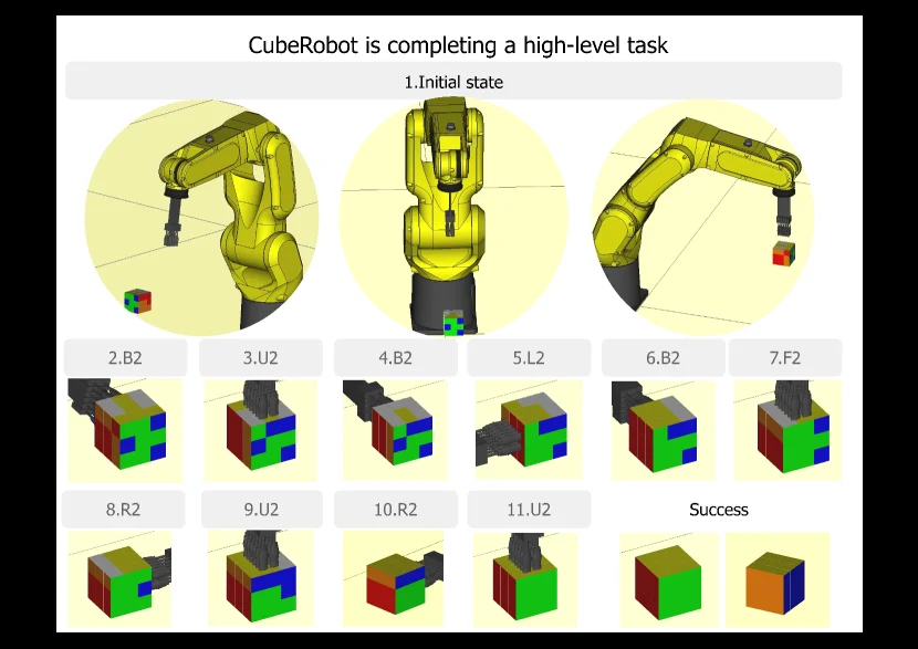
Figure 4. Visualization results of CubeRobot. We accurately emulated the movements of the CubeRobot equipped with LR Mate 200iD robotic arm.

This figure (Figure 4) visually demonstrates the workflow and results of the CubeRobot system while completing a high-level task. The figure aims to illustrate how CubeRobot, through its vision-language model (VLM) capabilities, plans and executes a sequence of actions to solve a Rubik's Cube problem.

First, the top title, "CubeRobot is completing a high-level task," clarifies that this is a demonstration of a high-level task. The figure is divided into several main sections:

  1. Initial State: This row contains three circular areas, from left to right, showing the initial conditions of the task:

    • The first circular area displays a yellow robotic arm (LR Mate 200iD) and an unmanipulated Rubik's Cube, with the cube located to the left of the arm. This represents the starting scene of the task.
    • The second circular area is a front view of the robotic arm, possibly to show its current pose or readiness state.
    • The third circular area shows the robotic arm having grasped the cube, or the cube being moved into the arm's operational range, ready to begin the task.
  2. Action Sequence and Intermediate States: Below the initial state, there is a series of numbered boxes (from 2.B2 to 11.U2), each containing an image of the Rubik's Cube. These boxes represent the sequence of steps executed by CubeRobot:

    • The number above each box (e.g., 2, 3, 4...11) indicates the order of the step.
    • The letter-number combination after the number (e.g., B2, U2, L2, R2, F2) typically represents a Rubik's Cube move instruction. For example, B2 might mean rotating the back face 180 degrees, and U2 means rotating the top face 180 degrees. These instructions are generated by CubeRobot's planning module.
    • The image of the cube within each box shows the state of the cube after the corresponding step is executed. By observing these images, one can see how the color blocks on the cube's surface change with each operation. This visualizes the decision-making and execution process of CubeRobot.
  3. Success State: On the far right of this row, there are two images of the Rubik's Cube, both labeled "Success." These images show the final state after the task is completed:

    • The left "Success" image displays a solved Rubik's Cube (e.g., one face might be entirely green, another might be a combination of red and green, depending on the initial state and task goal).
    • The right "Success" image might show another perspective of the completed cube, another aspect of completion, or an idealized final state (such as orange and blue faces). This indicates that CubeRobot has successfully completed the given high-level task, restoring the cube to the desired state.

Revelation of Method Operation: This figure reveals how CubeRobot operates as follows: * Perception and Understanding: The system first perceives the initial state of the Rubik's Cube (as shown in the first circular area). * Planning: Based on visual input and the task goal, CubeRobot's VLM performs independent planning, generating a sequence of action instructions (like B2, U2, etc.). These instructions correspond to cube rotations. * Execution: The robotic arm executes the corresponding actions according to the planned sequence of instructions, gradually changing the state of the cube (as shown in the various boxes in the middle row). * Reflection and Management: The system may perform reflection and adjustments during execution (though not directly shown in the figure, the paper mentions this) to ensure the task progresses correctly. * Task Completion: Ultimately, by executing the planned sequence of actions, the Rubik's Cube is successfully solved (as shown in the "Success" section).

This figure, through a specific example, demonstrates how CubeRobot decomposes a high-level task goal into executable low-level actions and completes complex cube manipulation tasks using its vision-language model and execution capabilities. It emphasizes CubeRobot's ability to handle high-level tasks that are challenging for humans.

Interpretation of the Result Figure: This figure itself is a result display, proving that CubeRobot can successfully complete a high-level Rubik's Cube task. By showing the complete process from the initial state to the final successful state, the data in the figure (i.e., the changes in the cube's state) clearly demonstrates the effectiveness of the method. The conclusion is that CubeRobot can effectively manipulate the Rubik's Cube and reach the desired target state through the planned sequence of steps.

← → flip · ↑ ↓ scroll notes · Esc exit