🌊 Tide

Information moves like the tide. We pick the waves worth studying.

中文

← Today's tide

Published 2026-06-17 · Tsinghua University · Youhe Jiang, Haoxu Wang, Haotong Bao et al.

TurboServe: Serving Streaming Video Generation Efficiently and Economically

arXiv · HuggingFace · ▲30

Abstract (verbatim)

Streaming video generation is emerging as a new serving workload in which users interact with long-lived sessions that generate video progressively, chunk by chunk. Unlike offline video generation or typical LLM serving, streaming video generation must preserve session state across active and idle periods, repeatedly schedule ongoing sessions, and deliver each chunk under a tight latency target. This creates two key serving challenges in multi-user, multi-GPU environments: session duration heterogeneity, where long-running sessions make placement decisions suboptimal over time, and temporal user-demand heterogeneity, where the number of active sessions fluctuates sharply across bursts and idle periods. We present TurboServe, the first serving system designed specifically for streaming video generation workloads. TurboServe formulates serving as an online scheduling problem that jointly coordinates session placement and GPU provisioning. Its closed-loop scheduling algorithm combines a migration-aware placement controller, which rebalances sessions across GPUs to reduce the maximum per-chunk latency, with a load-driven autoscaling controller, which adapts the GPU budget to workload variation for improved cost efficiency. To support these decisions at runtime, TurboServe implements coalesced chunk processing for batching concurrent active sessions on the same GPU, GPU-CPU offloading for session suspension and resumption, and NCCL-based GPU-GPU migration for online rebalancing. We evaluate TurboServe on real-world production traces from Shengshu Technology across multiple model sizes and GPU clusters with up to 64 NVIDIA B300 GPUs. Compared with baseline serving configurations, TurboServe reduces worst-case per-chunk latency by 37.5% and total GPU operating cost by 37.2% on average. Our code is publicly available at https://github.com/shengshu-ai/TurboServe.

Background

Background Analysis

1. Technical Context

With the advancement of video generation models (e.g., Sora, Veo), streaming video generation has emerged as a new paradigm in generative AI services. This technology allows users to progressively generate video chunks (e.g., frame-by-frame or second-by-second) and adjust content in real time (e.g., modifying scenes or characters). The core requirement is low-latency interactive generation—users expect to see video output as it is being created, rather than waiting for the entire video. Typical applications include film production (real-time special effects preview), advertising (dynamic creative adjustments), or educational content creation (instant feedback on teaching videos). However, traditional video generation systems (e.g., Sora) use an "offline batch generation" mode, which cannot support such long-term interactive scenarios, necessitating specialized streaming platforms.

2. Previous Limitations

Existing systems face two major challenges:
- Session Duration Heterogeneity: Sessions vary drastically in duration (from seconds to hours). Traditional systems treat all sessions as "short tasks," leading to long sessions monopolizing resources and blocking new users.
- Temporal Demand Fluctuations: User activity is bursty (e.g., high demand during peak hours, low demand during off-peak hours). Static resource allocation either wastes GPUs (during low demand) or causes latency spikes (during high demand) due to insufficient resources.
Previous methods failed to optimize for "persistent session states" and "dynamic loads," resulting in increased latency and cost inefficiency.

3. Proposed Solution

TurboServe addresses these issues by jointly scheduling session placement and GPU resource allocation:
- Dynamic Session Migration: Uses NCCL (high-speed GPU communication) to migrate sessions between GPUs, preventing long sessions from blocking resources.
- Elastic Resource Allocation: Automatically scales GPU counts based on real-time load (e.g., adding GPUs during peak hours to reduce latency, releasing them during off-peak hours to save costs).
- Batching and Suspension Mechanisms: Merges computations of multiple active sessions (batching) to improve GPU utilization and allows idle sessions to temporarily move to CPU memory to free up GPU resources.

4. Unique Approach

Unlike existing systems, TurboServe is the first system explicitly designed for streaming video generation, with a key innovation in treating "session management" and "resource scheduling" as a unified problem. Traditional methods (e.g., vLLM-Omni or TridentServe) only optimize single requests, while TurboServe balances latency and cost through a closed-loop algorithm. For example:
- Migration-Aware Scheduling: Dynamically adjusts session locations to minimize worst-case latency.
- Load-Driven Scaling: Adjusts GPU counts based on real-time demand, rather than static configurations.
Experiments show TurboServe achieves 37.5% lower worst-case chunk latency and 37.2% lower GPU operating costs on average compared to baselines.
Method, Figure by Figure

M E T H O D1 / 5

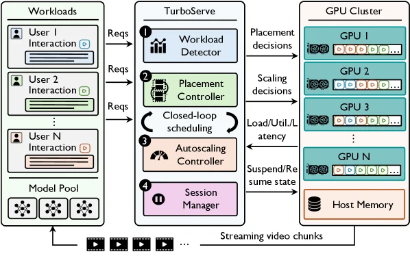
Figure 5 : TurboServe system overview. TurboServe processes streaming requests and session events through a closed-loop scheduler that places and migrates sessions across GPU workers, adjusts GPU provisioning, and offloads suspended states to host memory. Runtime load, utilization, and latency feedback guide these decisions to balance serving latency and GPU cost.

This diagram illustrates the overall architecture and workflow of the TurboServe system, designed for efficiently and economically handling streaming video generation services.

First, let's look at the "Workloads" section on the left. This represents interaction requests from multiple users (User 1, User 2, ..., User N) and a "Model Pool" containing models for video generation. User interaction requests (Reqs) are sent to the TurboServe system in the middle.

Next is the core part of TurboServe in the middle, which includes four main components numbered 1 to 4:

  1. Workload Detector: This component receives requests (Reqs) from users and detects the current workload. It analyzes information such as the number, type, and frequency of requests.
  2. Placement Controller: Based on the results from the Workload Detector, the Placement Controller decides which GPU to execute each video generation session on. Its goal is to optimize session placement to minimize maximum latency per video chunk.
  3. Autoscaling Controller: This component dynamically adjusts the resource provisioning of GPUs based on feedback like load, utilization (Load/Util/Latency). When the workload increases, it adds more GPU resources or increases their quantity; when the workload decreases, it reduces GPU resources to improve cost efficiency.
  4. Session Manager: The Session Manager manages the lifecycle of sessions, including suspending (Suspend) and resuming (Resume) them. It saves the state of sessions to host memory so they can be resumed when needed.

Then, we have the "GPU Cluster" section on the right. It contains multiple GPUs (GPU 1, GPU 2, ..., GPU N) and host memory. TurboServe allocates video generation sessions to different GPUs for execution based on the Placement Controller's decisions. Meanwhile, the Autoscaling Controller adjusts GPU resources or quantity according to load conditions. The Session Manager saves the state of suspended sessions to host memory and resumes them when necessary.

The flow of data or information is as follows:

  1. User interaction requests (Reqs) are sent from the "Workloads" section on the left to the "Workload Detector" in TurboServe.
  2. The "Workload Detector" detects the workload and passes the information to the "Placement Controller".
  3. The "Placement Controller" makes placement decisions based on the workload and assigns video generation sessions to different GPUs for execution.
  4. The "Autoscaling Controller" makes scaling decisions based on feedback like load and utilization, adjusting the resource provisioning of GPUs.
  5. The "Session Manager" manages the session lifecycle, including suspension and resumption, and saves session states to host memory.
  6. Each GPU in the GPU cluster executes the assigned video generation sessions and generates video chunks.
  7. Video chunks are transmitted back to users via streaming (Streaming video chunks).

This diagram reveals how the TurboServe method works:

  • Closed-loop scheduling: TurboServe uses a closed-loop scheduling algorithm to coordinate session placement and GPU resource configuration. This algorithm combines a migration-aware placement controller and a load-driven autoscaling controller.
  • Migration-aware placement controller: This controller rebalances sessions across GPUs to reduce maximum latency per video chunk. It considers migration costs to ensure the benefits of rebalancing outweigh the costs.
  • Load-driven autoscaling controller: This controller dynamically adjusts GPU resource provisioning based on workload changes. It increases GPU resources or quantity when the workload grows and reduces them when the workload decreases to improve cost efficiency.
  • Runtime feedback: TurboServe uses runtime load, utilization, and latency feedback to guide these decisions, balancing service latency and GPU costs.

Additionally, the diagram mentions some technical details:

  • Coalesced chunk processing: Used to batch concurrent active sessions on the same GPU for improved efficiency.
  • GPU-CPU offloading: Used to offload session states to host memory to support session suspension and resumption.
  • NCCL-based GPU-GPU migration: Used for online session rebalancing to enhance performance.

In summary, this diagram provides a detailed view of the TurboServe system's architecture and workflow, explaining how it efficiently and economically handles streaming video generation services through closed-loop scheduling, a migration-aware placement controller, and a load-driven autoscaling controller.

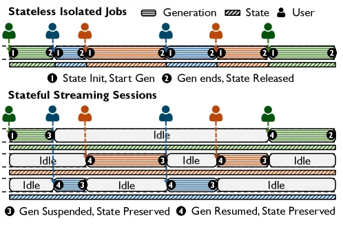
Figure 1 : Stateless isolated generation jobs ( top ) compared with stateful streaming generation sessions ( bottom ) in multi-user scenarios. In stateless generation, each user request initializes temporary generation state, starts generation, and releases the state once the generation job completes. In stateful streaming generation, each user corresponds to a persistent session that alternates between active generation and idle periods; generation can be suspended and later resumed while preserving the session state across periods.

This diagram (Figure 1) visually illustrates the unique challenges and core design principles of streaming video generation services by comparing two different computational task models.

First, let's look at the upper part of the diagram, titled "Stateless Isolated Jobs." This section describes a traditional stateless computational model. There are five parallel timelines, each representing a user (indicated by different colored human icons: green, blue, orange). Time flows from left to right.

  • Components and Processes:
    • Activities on each timeline are divided into several stages. The first is "① State Init, Start Gen" (State Initialization, Start Generation), which means that when a user request arrives, the system initializes a new generation state and begins executing the generation task. This stage is represented by a solid colored block (the color corresponds to the user).
    • Next is "② Gen ends, State Released" (Generation Ends, State Released), which indicates that after the generation task is completed, the system releases the state resources occupied by the task. This stage is also represented by a solid colored block, usually with a similar or slightly different color from the previous stage for distinction.
    • Between these activities, the timeline is blank, indicating no active generation tasks.
    • In the legend, "Generation" is represented by a solid block, and the concept of "State" is implicit in the start and end of tasks because the stateless model releases the state after the task ends.
    • Arrow or process order: A user request (human icon) triggers state initialization and the start of the generation task. After the generation task is completed, the state is released, and then it waits for the next request (if any).

This part reveals the characteristics of stateless jobs: each request is independent, has its own temporary state, and the state is released after the task is completed, so resources can be reused.

Next, let's look at the lower part of the diagram, titled "Stateful Streaming Sessions." This part describes the service model of streaming video generation, which forms a sharp contrast with the upper part.

  • Components and Processes:
    • Similarly, there are five parallel timelines, each representing a user's persistent session.
    • The activities of each session are divided into two states: "active generation" and "Idle."
    • "③ Gen Suspended, State Preserved" (Generation Suspended, State Preserved): When the session is in the idle period, the generation process is suspended, but the session state is preserved. In the diagram, this is represented by a lighter, possibly striped or dashed block, or simply marked as "Idle" but clearly indicating that the state is preserved.
    • "④ Gen Resumed, State Preserved" (Generation Resumed, State Preserved): When the session becomes active again, the generation process resumes from where it was paused before, and the state remains unchanged. This is also represented by a block, possibly with a color related to the previous active period.
    • The legend clearly marks "③ Gen Suspended, State Preserved" and "④ Gen Resumed, State Preserved."
    • Arrow or process order: After a user establishes a session with the system, it goes through multiple alternations between active and idle periods. During the active period, video chunks are generated; during the idle period, the generation is suspended but the state is preserved for quick recovery later.

This part reveals the core characteristics of stateful streaming sessions: sessions are persistent and span multiple active and idle cycles. The key point is that during the idle period, the session state is preserved, so when the user requests again, the generation can continue from where it was interrupted last time without starting over. This brings two main challenges: the heterogeneity of session duration (long sessions may cause resource allocation to become suboptimal over time) and the heterogeneity of user demand over time (the number of active sessions fluctuates drastically between peak and idle periods).

Explanation of How the Method Works: Through comparison, this diagram explains why streaming video generation services require special design. The stateless model is not suitable because it cannot handle tasks that need to continue over multiple cycles, and releasing the state between tasks leads to the overhead of restarting.

The TurboServe method is designed to solve these problems: 1. Persistence of Sessions and State Preservation: As shown in the lower part of the figure, the system needs to support sessions switching between active and idle while preserving the state. This means that the system needs mechanisms to pause and resume the generation process without losing intermediate results or context. 2. Online Scheduling Algorithm: To deal with the heterogeneity of session duration and fluctuations in user demand, TurboServe models the service as an online scheduling problem that jointly coordinates session placement (which session to put on which GPU) and GPU resource allocation (increasing or decreasing GPUs based on load). * Migration-Aware Placement Controller: To reduce the latency of each video chunk, the system needs to rebalance sessions among multiple GPUs. Although the migration process is not directly shown in the diagram, the technology of "NCCL-based GPU-GPU migration for online rebalancing" is for this purpose. When a certain GPU is overloaded or a session runs inefficiently on the current GPU, it can be migrated to another GPU. * Load-Driven Auto-Scaling Controller: To improve cost efficiency, the system needs to adjust GPU resources according to changes in workload. Increase the GPU budget when the number of active sessions increases; decrease the GPU budget when the number of sessions decreases. 3. Runtime Support Technologies: * Merged Chunk Processing: To batch process concurrent active sessions on the same GPU to improve efficiency. * GPU-CPU Offloading: Used for session suspension and resumption. When a session needs to be suspended, its state can be offloaded to CPU memory, thus releasing GPU resources for other active sessions. When the session needs to be resumed, the state can be loaded back from CPU memory to the GPU. * NCCL-based GPU-GPU Migration: Used for online rebalancing of sessions, as mentioned above.

In summary, through comparing stateless jobs and stateful streaming sessions, this diagram clearly shows the uniqueness of streaming video generation services: it needs to manage persistent sessions that have high dynamics and heterogeneity in terms of time and resource usage. The design of TurboServe is precisely to efficiently handle these characteristics, achieving low-latency and high-cost-effective video streaming generation services through intelligent scheduling, resource management, and specific runtime technologies.

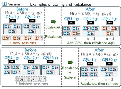
Figure 6 : Illustrative examples of closed-loop GPU autoscaling and session rebalancing. The top example shows scale-out followed by session rebalancing, where new GPUs are added and sessions are redistributed to reduce load concentration. The bottom example shows rebalancing followed by scale-in, where sessions are first consolidated onto fewer GPUs before underutilized GPUs are removed.

This diagram illustrates, through two concrete examples, how the "closed-loop GPU auto-scaling with session rebalancing" mechanism proposed in the paper "TurboServe: Serving Streaming Video Generation Efficiently and Economically" operates. We can understand it by dividing it into two parts:

Upper Part: Rebalance after Scale-out

  1. "Before" State:

    • The system currently has M(t) = 2 GPUs (G(t) = {g₁, g₂}).
    • GPU 1 (g₁) is running sessions S₁, S₂, S₃.
    • GPU 2 (g₂) is running sessions S₄, S₅, S₆.
    • At this point, 4 new sessions (S₇, S₈, S₉, S₁₀, indicated by dashed boxes) are about to arrive, and the system needs to handle this increased load.
    • The label "n = 4" likely refers to the current number of sessions per GPU or some unit of resource allocation.
  2. Operation Flow (indicated by arrows):

    • A green arrow points to the right, labeled "Scale-out + Rebalance." This indicates that the system first performs a scale-out operation, followed by rebalancing.
  3. "After" State:

    • The system has added 1 new GPU, so there are now M(t) = 3 GPUs (G(t) = {g₁, g₂, g₃}).
    • The new GPU 3 (g₃) has been added.
    • Sessions are now redistributed:
      • GPU 1 (g₁) is running S₁, S₂, S₃, S₁₀.
      • GPU 2 (g₂) is running S₄, S₅, S₆.
      • GPU 3 (g₃) is running S₇, S₈, S₉.
    • The purpose is "Add GPU, then rebalance φ(t)" (add GPU, then rebalance φ(t)). By redistributing new and existing sessions across more GPUs, the load concentration on individual GPUs is reduced, thereby lowering the latency of each video chunk.
    • The labels "n = 4" and "n = 3" indicate the number of sessions on GPU 1 and GPU 2 after scaling, respectively, while GPU 3 has 3 sessions.

Lower Part: Scale-in after Rebalance

  1. "Before" State:

    • The system currently has M(t) = 3 GPUs (G(t) = {g₁, g₂, g₃}).
    • GPU 1 (g₁) is running sessions S₁, S₂, S₃, S₁₀.
    • GPU 2 (g₂) is running sessions S₄, S₅, S₆.
    • GPU 3 (g₃) is running sessions S₇, S₈, S₉.
    • At this point, 3 sessions (S₆, S₉, S₁₀, indicated by dashed boxes) have completed, and the system needs to handle the reduced load.
    • The labels "n = 4" and "n = 3" indicate the number of sessions on GPU 1 and GPU 2, respectively, while GPU 3 has 3 sessions.
  2. Operation Flow (indicated by arrows):

    • A green arrow points to the right, labeled "Rebalance + Scale-in." This indicates that the system first performs a rebalancing operation, followed by a scale-in.
  3. "After" State:

    • The system has removed 1 GPU, so there are now M(t) = 2 GPUs (G(t) = {g₁, g₂}).
    • The removed GPU is g₃.
    • Before removing the GPU, sessions are redistributed:
      • GPU 1 (g₁) is running S₁, S₂, S₃, S₈.
      • GPU 2 (g₂) is running S₄, S₅, S₇.
    • The purpose is "Rebalance, then remove" (rebalance, then remove). By migrating sessions originally on the GPU to be removed (g₃) (S₇, S₈, S₉) to the remaining GPUs, it ensures that no sessions are lost when the GPU is removed, and the load remains balanced.
    • Ultimately, after the load decreases, the system improves cost efficiency by reducing the number of GPUs.

Method Operation Revealed:

This diagram clearly demonstrates the core ideas of TurboServe: * Dynamic Scaling: The system can dynamically increase or decrease GPU resources based on changes in load (such as the arrival of new sessions or the completion of existing ones). * Session Rebalancing: Before or after scaling GPUs, the system migrates and redistributes sessions among GPUs to optimize load balancing, reduce the burden on individual GPUs, and thus lower latency. * Closed-loop Scheduling: This is a closed-loop system because it considers both session placement and GPU resource provisioning simultaneously. When load increases, it scales out first and then rebalances; when load decreases, it rebalances first and then scales in. This strategy ensures that the system can effectively handle requests under high load and save costs under low load.

In summary, this diagram vividly explains, through specific examples, how TurboServe coordinates session placement and GPU resource management to handle dynamic load changes in streaming video generation tasks, achieving efficient and economical video generation services.

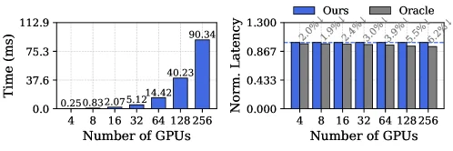
Figure 9 : Left: Scheduling efficiency of the migration-aware min-max rebalancing. Right: Scheduling effectiveness of the migration-aware min-max rebalancing (vs. oracle).

This figure contains two subplots, each illustrating the scheduling efficiency and effectiveness of the "migration-aware min-max rebalancing" mechanism in the TurboServe system.

Left Subplot: Scheduling Efficiency * X-axis: Represents the number of GPUs, ranging from 4 to 256 (4, 8, 16, 32, 64, 128, 256). This denotes the scale of computational resources available in the system. * Y-axis: Represents time in milliseconds (ms). Specifically, it refers to the time required to complete a scheduling operation or achieve a certain balance state. * Data Series: The blue bars represent the execution time of the "migration-aware min-max rebalancing" mechanism in TurboServe for different numbers of GPUs. * Data Interpretation: * As the number of GPUs increases, the scheduling time also increases significantly. For instance, when the number of GPUs grows from 4 to 256, the time increases from 0.250 ms to 90.34 ms. * This indicates that the computational complexity of the rebalancing mechanism rises with the number of GPUs, but even in a large-scale scenario with 256 GPUs, the time taken (approximately 90ms) is within an acceptable range, suggesting the method is feasible for large clusters. * Method Operation Revealed: This subplot shows the computational cost of the "migration-aware min-max rebalancing" mechanism in practice. By measuring the time taken to complete rebalancing under different scales, it evaluates the mechanism's efficiency. Shorter time implies higher efficiency. The data shows that although time increases with more GPUs, the method can operate efficiently in large-scale clusters overall.

Right Subplot: Scheduling Effectiveness * X-axis: Also represents the number of GPUs, from 4 to 256. * Y-axis: Represents normalized latency (Norm. Latency). This means the latency values have been standardized, typically by comparing actual measured latency to a baseline (e.g., the latency of the "Oracle" method). All values shown are less than 1, indicating that "Ours" (TurboServe's method) has latency equal to or better than the baseline. * Data Series: * The blue bars represent TurboServe's method (labeled "Ours"). * The gray bars represent an ideal "Oracle" method (labeled "Oracle"), which might assume perfect foresight or optimal resource allocation. * The small percentage numbers above each bar (e.g., 2.0%, 1.9%) indicate the percentage increase in latency of "Ours" relative to "Oracle". For example, at 4 GPUs, "Ours" has a 2.0% higher latency than "Oracle". * Data Interpretation: * For all tested numbers of GPUs, the normalized latency of "Ours" (TurboServe) is very close to that of "Oracle". * The percentage increase in latency is very small, typically around 2% or less (e.g., 2.2% at 256 GPUs). * This indicates that the "migration-aware min-max rebalancing" mechanism in TurboServe is highly effective in reducing latency, achieving performance very close to the theoretical optimum (Oracle). * Method Operation Revealed: This subplot evaluates the scheduling effectiveness of TurboServe's method by comparing its latency with that of the ideal Oracle method. The results show that TurboServe's method can achieve near-theoretical-optimal performance in practice, demonstrating its efficiency and effectiveness. It successfully balances the load across different GPUs, thereby minimizing overall latency.

Summary: This figure demonstrates the performance of the "migration-aware min-max rebalancing" mechanism in TurboServe from two aspects: scheduling efficiency and scheduling effectiveness. The left plot shows that the computational overhead of this mechanism increases with the number of GPUs but remains manageable in large-scale scenarios. The right plot shows that the mechanism is highly effective in reducing latency, with performance very close to the ideal Oracle method. Collectively, this figure strongly proves that the scheduling strategy employed by TurboServe is both efficient and effective.

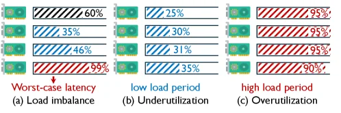
Figure 3 : Illustration of the observations. ( a ) Evolving session activity causes load imbalance across GPUs, where the most heavily loaded GPU determines the worst-case per-chunk latency. ( b ) During low-demand periods, a fixed GPU allocation leads to resource underutilization. ( c ) During high-demand periods, the same static allocation becomes overutilized, resulting in high per-chunk latency.

This figure (Figure 3) intuitively illustrates key observations in streaming video generation serving, which are the core challenges TurboServe aims to address. Let’s analyze each subplot:

Subplot (a): Load Imbalance

This subplot (labeled “Load imbalance”) shows how evolving session activity (dynamic changes in session behavior) causes uneven load distribution across GPUs. Four GPUs (green graphics) are shown, each with a progress bar indicating load percentage:
- Top GPU: 60% load (black diagonal fill).
- Second GPU: 35% load (blue diagonal fill).
- Third GPU: 46% load (blue diagonal fill).
- Bottom GPU: 99% load (red diagonal fill, with an arrow pointing to it labeled “Worst - case latency”).

The logic is: As sessions progress (activity evolves), GPU loads become unbalanced. The heaviest - loaded GPU (here, the bottom one with 99% load) determines the worst - case per - chunk latency—even if other GPUs are underutilized, the entire system’s latency is bottlenecked by the busiest GPU. This reflects the “session duration heterogeneity” challenge (long - running sessions make static placement suboptimal over time).

Subplot (b): Underutilization (Low - Load Period)

Subplot (b) (labeled “Underutilization”) corresponds to a low - demand period. Four GPUs are shown with low load percentages (all blue diagonal fills): 25%, 30%, 31%, and 35%.

Here, all GPUs have far less than full load (e.g., < 50% on average). This shows that with a fixed GPU allocation (no dynamic adjustment), resources are wasted during low - demand periods—many GPUs’ computing power is underutilized. This reflects the “temporal user - demand heterogeneity” challenge (idle periods with static allocation lead to inefficiency).

Subplot (c): Overutilization (High - Load Period)

Subplot (c) (labeled “Overutilization”) corresponds to a high - demand period. Four GPUs have high load percentages (all red diagonal fills): 95%, 95%, 95%, and 90%.

Here, all GPUs are nearly full - loaded. This shows that with a fixed GPU allocation, resources are overutilized during high - demand periods—each GPU is saturated, leading to high per - chunk latency (since GPUs cannot process new tasks quickly). This also reflects the “temporal user - demand heterogeneity” challenge (burst periods with static allocation cause overload).

Overall Message (Link to TurboServe)

The figure demonstrates three problems in streaming video generation serving:
1. Load imbalance (subplot a): Static placement fails to balance load, bottlenecking latency via the heaviest GPU.
2. Underutilization (subplot b): Fixed GPU allocation wastes resources during low demand.
3. Overutilization (subplot c): Fixed GPU allocation causes overload (and high latency) during high demand.

TurboServe addresses these via:
- A migration - aware placement controller (to rebalance sessions across GPUs, solving subplot a’s imbalance).
- A load - driven autoscaling controller (to adjust GPU budget, solving subplot b’s underutilization and subplot c’s overutilization).

In short, the figure visually proves that static resource management (fixed placement/allocation) is inefficient in multi - user, multi - GPU streaming video generation, motivating TurboServe’s dynamic scheduling approach.

← → flip · ↑ ↓ scroll notes · Esc exit